SMN-Tape Feeder Manual(Eng Ver5).pdf - 第39页
Operation of the T ape Feeder 2-9 Ensure that the tape guide and the locker are properly locked. Figur e 2-13. Checking the locking state of t he tape guide and the locker (SM 12mm~16mm t ape feeder) Figur e 2-14. Checki…
Samsung SM-Series Pneumatic Tape Feeder Users' Manual
2-8
Adjust while pulling the upper cover tape backward to fit to the slot of the tape guide.
Caution
Use after checking as the vinyl can become wound if the
upper cover tape is not setup to come out of the tape
guide smoothly.
Push locker in the direction of the tape guide and fix the tape guide and locker.
Caution
Be careful not to close the locker while the tape guide is
open.
Make final confirmation by checking if the tape is correctly setup in the tape guide and
frame, and checking if the sprocket is correctly protruding from the moving slot of the
transportation tape.
Figure 2-12. Confirm the setting of the tape guide, tape and frame (SM 8mm tape feeder)
Caution
If the transportation tape is incompletely attached by
correctly setting the transportation tape at the tape guide
& frame in the tape feeder, the tape may not be supplied
and the dump rate of the components may increase.
Therefore, ensure that they are tightly contacted prior to
using the tape feeder.
Tape
Frame
Tape Guide
Operation of the Tape Feeder
2-9
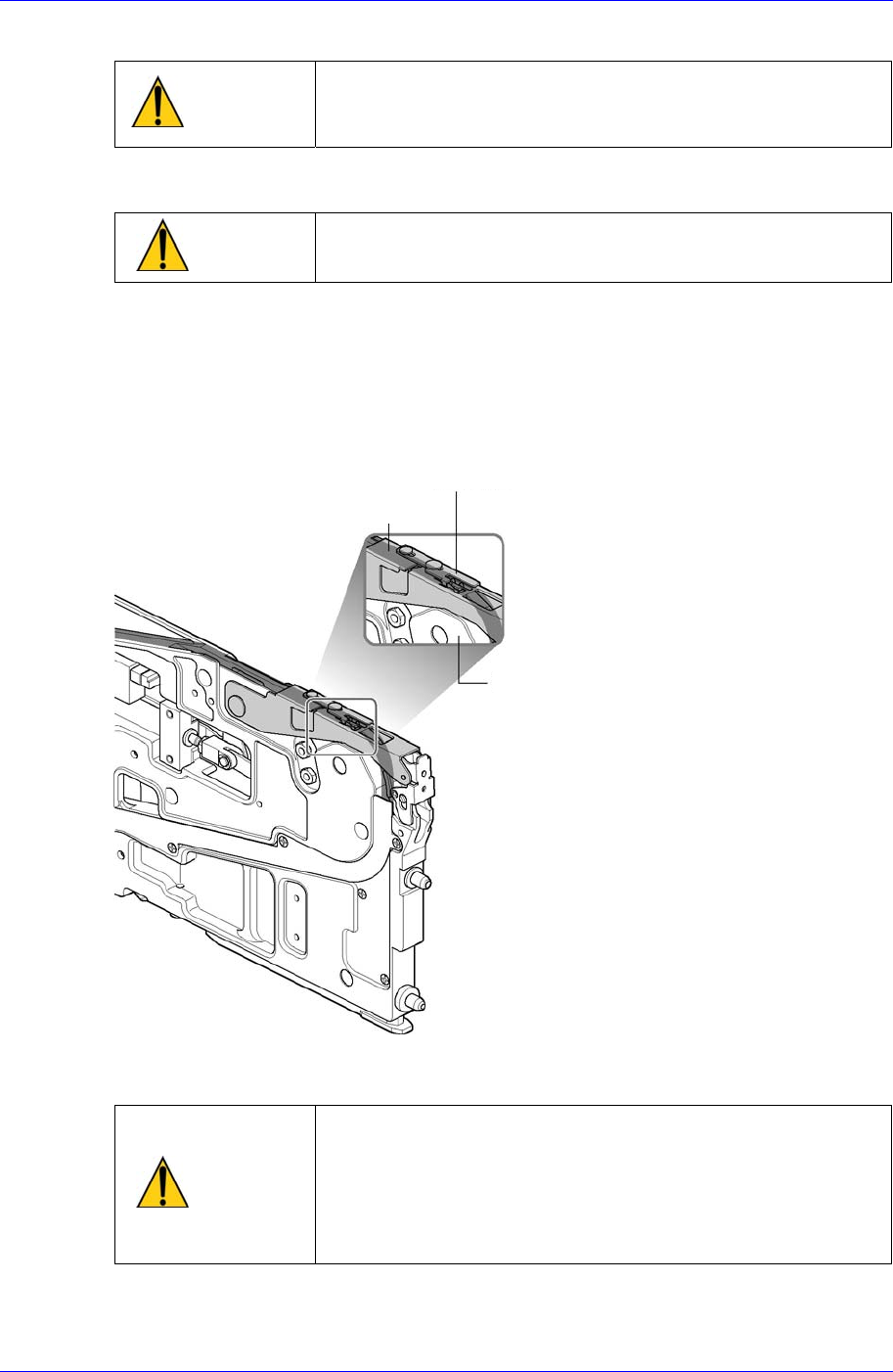
Ensure that the tape guide and the locker are properly locked.
Figure 2-13. Checking the locking state of the tape guide and the locker (SM 12mm~16mm tape
feeder)
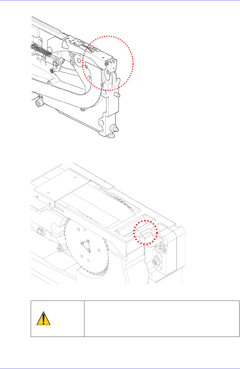
Figure 2-14. Checking the locking state of the tape guide and the locker (SM 24mm~88mm tape
feeder)
Caution
Check the locking state of the tape guide and the locker.
The tape feeder whose tape guide and lock cover are not
properly locked may cause problems such as lack of tape
supply or collision with the machine. Ensure that they are
properly locked prior to use.
Samsung SM-Series Pneumatic Tape Feeder Users' Manual
2-10
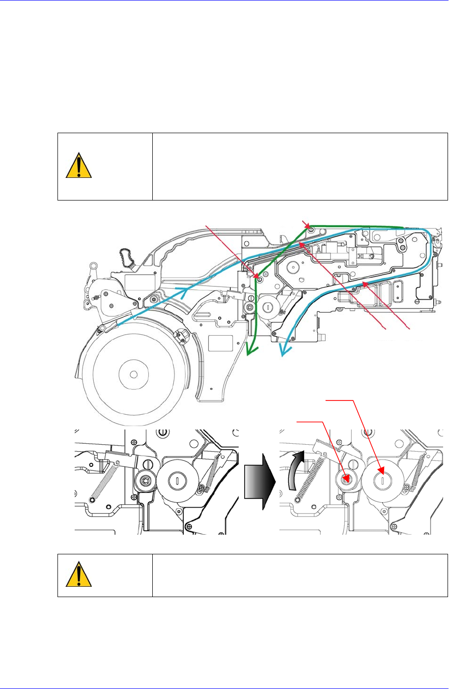
2.1.5. Fixing the Upper Cover Tape
8mm Tape Feeder
Fix the upper cover tape guide protruding from the tape separation slot. Put the SM
8mm tape feeder between the drain gear and forming gear while loading the upper
cover tape protruding from the tape guide separation slot on rollers A and B.
At this time, tightly pull the upper cover tape, position it between the afore-
mentioned two gears, and fix the upper cover tape. At this time, turn the drain gear
counterclockwise and pull it tight
Caution
When the upper cover tape passes roller B or passes
between the drain gear and forming gear, make it pass
flatly without folding or jumping over the roller or gear.
Take care as problems like vinyl rolling will transpire if
folding or deviation beyond the drain gear occurs.
Figure 2-15. Method of fixing upper cover tape in the roller and gear (SM 8mm tape feeder)
Caution
When the cover tape is fixed, be careful so that fingers
don’t get stuck between the forming gear and the drain
gear as the forming gear receives force from the spring.
12~16mm Tap Feeder
When placing the cover tape, be mindful of the direction of the cover tape as shown
in the figure, and ensure that the adhesive surface (surface attached to the
transportation tape) of the cover tape faces the direction of the forming gear.
Forming Gea
r
Drain Gea
r
Roller B
Roller A
Groove A
Groove B