JBC_PHXLE-K_manual.pdf - 第4页
4 Connection to Power Supply Peak Current Cable Connection Wire Section Single-pha se Three-pha se Single-pha se Three-pha se 230V 30 A 10 A 4mm 2 1 mm 2 1 0 0V/ 1 20V 60 A 20 A 10 m m 2 2,5 m m 2 PHXLE- K A can be conne…

3
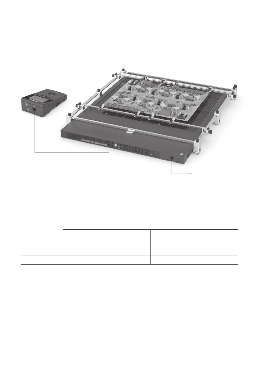
Features and Connections
Pedal Connector
Heating Areas
Main Switch
Fixing brackets for
XL PCB Support
Heater Unit
Zone B
Zone A
USB-B Connector
RJ45 Connector
to Console
RJ12 Connector
to Robot
Thermocouple
Connectors x8
(Type K)
Console
2,8” Color
TFT Screen
Start / Stop
USB-B Connector
RJ45 Connector
to Preheater Unit
USB-A Connector
Foot for Vertical Set Up
Button for Foot
Folding and
Unfolding
Support
Slot Clamps
Adjusting System
for Changing Height
Clamp Knobs
Sliding
Guides
Allen Key
For Electrical
Power Supply
Connection
www.jbctools.com
4
Connection to Power Supply
Peak Current Cable Connection Wire Section
Single-phase Three-phase Single-phase Three-phase
230V 30 A 10 A 4mm
2
1 mm
2
100V/120V 60 A 20 A 10 mm
2
2,5mm
2
PHXLE-KA can be connected to single-phase or three-phase networks. A power supply cable is
required. Use the following table to determine the cable size and connection:
Connection to
Power Supply
RJ45 Cable
Ref. 0 019914
PHXLE
PHXL-SA
PHB-SA
PHS-SA
PHN-SA
PHBE
PHSE
PHNE
OK
14:15
20
º
C
Power
45%
TC1
45
º
C
Selected 120
º
C
TC2
P
100
º
C
20
º
C
TC3
P
100
º
C
20
º
C
TC4
P
100
º
C
14:15
20
º
C
Power
45%
Selected power
45
%
TC1
P
100
º
C
20
º
C
TC3
P
100
º
C
20
º
C
TC4
P
100
º
C
20
º
C
TC2
P
100
º
C
14:15
20
º
C
T1
23
º
C
20
5’ 8’
º
C
120
º
C
T3
24
º
C
T7
StopPROFILE1
200
100
14:15
31
º
C
27
º
C
TC1
TC2
StopPROFILE1
200
100
14:15
200
150
100
50
300
250
14:15
5m 00s
120
º
C
PROFILE1
200
100
14:15
30
º
C
Power
45%
Selected power
45
%
TC1
C
100
º
C
---
º
C
TC2
P
100
º
C
0 60 120 180 240 300
Point
2/3
Temp Time
2m 00s
14:15
20
º
C
20
º
C
TC1
TC2
20
º
C
TC3
20
º
C
TC4
StopPROFILE1
200
100
Ext. Temp [ºC]Power [%]
14:15
20
º
C
Power
45%
TC1
45
º
C
Selected 120
º
C
TC2
P
100
º
C
20
º
C
TC3
P
100
º
C
20
º
C
TC4
P
100
º
C
14:15
20
º
C
Power
45%
TC1
45
º
C
Selected 120
º
C
TC2
C
100
º
C
20
º
C
TC3
P
100
º
C
20
º
C
TC4
P
100
º
C
14:15
20
º
C
Power
45%
Selected power
45
%
TC5
P
100
º
C
20
º
C
TC7
P
100
º
C
20
º
C
TC8
P
100
º
C
20
º
C
TC6
P
100
º
C
20
º
C
TC5
P
100
º
C
14:15
20
º
C
Power
45%
TC1
25
º
C
Selected 120
º
C
TC2
P
100
º
C
14:15
20
º
C
Power
45%
TC1
25
º
C
Selected 120
º
C
TC2
P
100
º
C
14:15
20
º
C
Power
45%
TC1
45
º
C
Selected 120
º
C
TC2
C
100
º
C
20
º
C
TC3
P
100
º
C
20
º
C
TC4
P
100
º
C
20
º
C
TC5
P
100
º
C
20
5’ 8’
º
C
120
º
C
80
º
C
100
º
C
5’ 8’5’30”3’30” 8’
20
º
C
120
º
C
80
º
C
Lorem ipsum
0025486
ETIQUETA CONEXIONADO PHXL
E 1:1
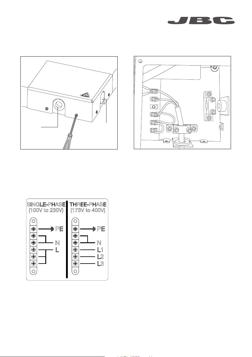
MONOPHASIC
(100V to 230V)
TRIPHASIC
(173V to 400V)
PE PE
N N
L L1
L2
L3
SINGLE-PHASE
(100V to 230V)
THREE-PHASE
(173V to 400V)
PE PE
N N
L L1
L2
L3
5
To conect your power supply cable to the Heater Unit do as follows:
1. Unscrew the four screws and remove the
cover. The cable can be inserted through the
front or the side part of the Heating Unit, all you
have to do is replace the cap with the cable
grommet.
2. Insert the cable through the cable grommet
and the flange and fix it with the allen screws.
(Image shows single phase connection).
3. Connect the cables as the Scheme and
reassemble.
Cable
grommet
Cap
www.jbctools.com