SIPLACE HS50 电路图 - 第106页
2 Circuit Diagr ams 106 I 0033618 2-030 102LD3 Di stributo r , sector 3 1 X300 terminals overview CAN bus X3cg X2cg F B 500kbps 3 2 1 4 5 6 7 ab c CAN bus 500kbps +5V B10 B11 B12 B2 00332557 ( cg) 2 X4cg Locking clip plu…
2 Circuit Diagrams 105
I
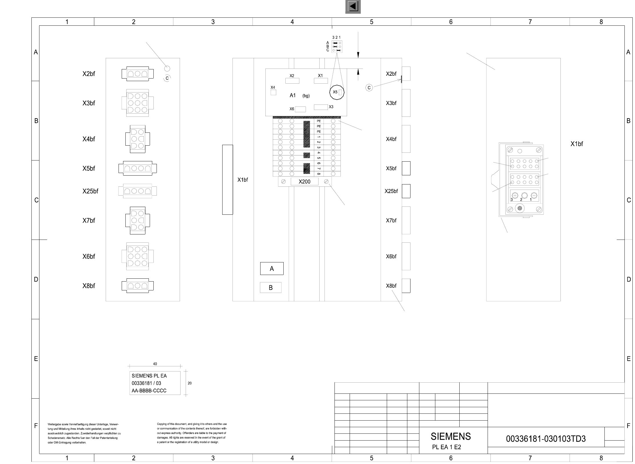
00336181-030103TD3 Distributor, sector 2
SMD Placement System SIPLACE HS50
Distributor, sector 2
Font size 2.5 mm, material Scotchal 3698-E (color A1 RAL 9006)
BBBB = Date (year/month/day) acc. to SN 01007
CCCC = Manufacturer/location of plant acc. to SN 37040
Identification: testing engineer, month, year
C: PE label (gn/ye)
B: Inspection label
AA = Numerals
The ’PE terminal block’ and the ( 1 2 3 ... ) terminals
will be connected with an additional yellow/green jumper.
and 2 grey 3-pole terminal blocks with 2 yellow/green jumpers.
’PE terminal block’ made of a yellow/green 3-pole terminal block
Document status
Product status
Function status
Assembly inscription acc. to VA-F-510-001
The following labels have to be applied:
A: Identification label
* Please note!
Ground hole
font size 4 mm
Plug inscription on edge,
Part 002
gn/ye
Bracket
Pin12
Pin12
Part 001
Module A
Module B
Pin1
Pin1
Pneumatic module
(Pins 1 and 3 are wired)
Status Modified Date Name
Author
Check.
Stand.
Date
Name
(Drawing number)
Main no.
Sheet
Sh.
CAN bus coupler for component table 2
Jumper configuration
10.04.00
03.
01.
Tek
Tek
Tek
10.04.00
21.04.99
21.04.99
Hoffmann14.01.1998
03.
1
A3
1
7
FSUAUSESFS
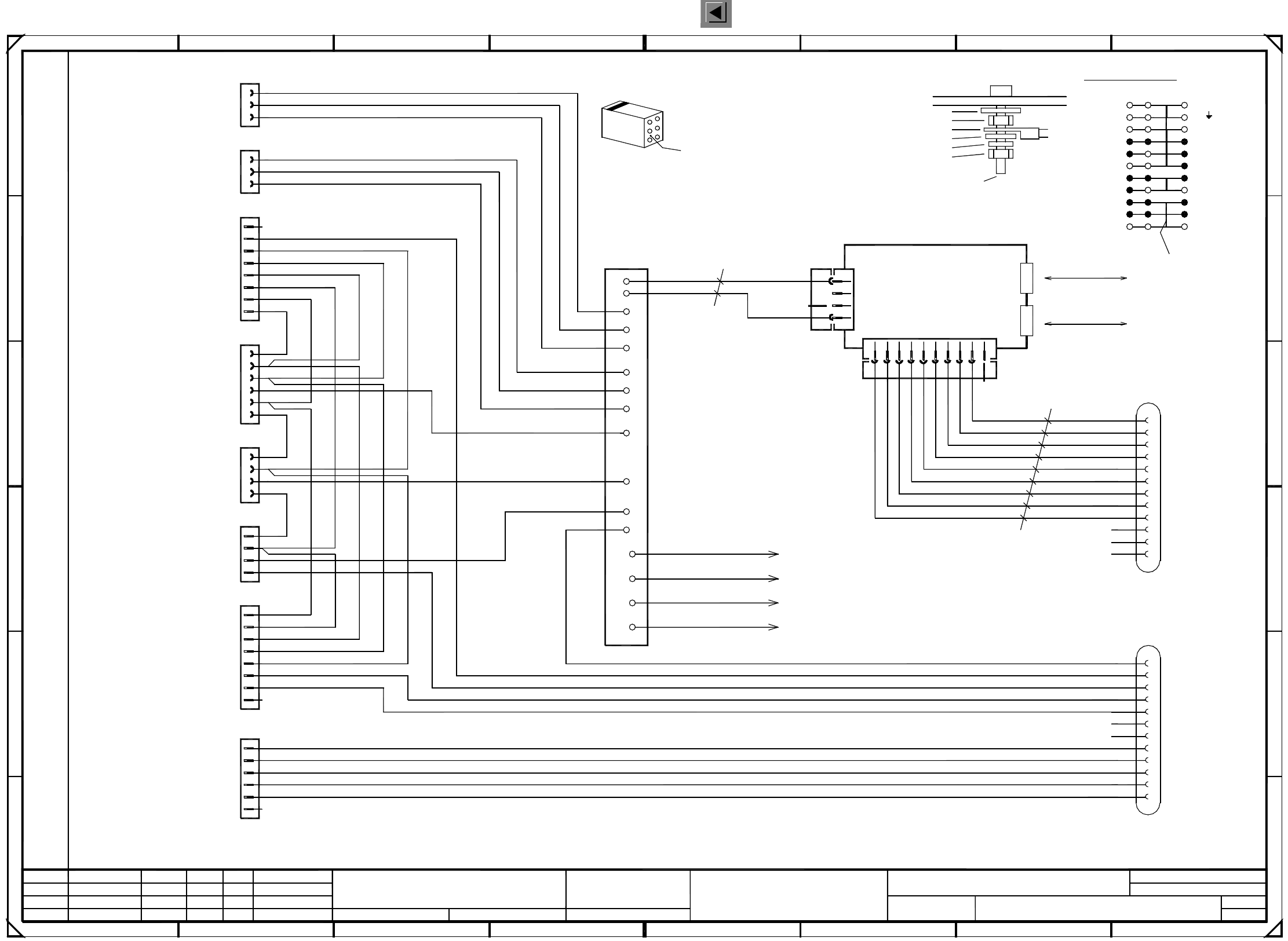
2 Circuit Diagrams 106
I
00336182-030102LD3 Distributor, sector 3
1
X300 terminals overview
CAN bus
X3cg
X2cg
F
B
500kbps
32
1
4
5
6
7
ab c
CAN bus
500kbps
+5V
B10
B11
B12
B2
00332557 (cg)
2
X4cg
Locking clip plug:
key
key
B module
X1cf
B1
B6
B8
CANH
CAN_INT
CANL
C
D
E
10
2
3
A1 CAN-bus coupler
X3cg and X4cg
3
2
8
78
A
X300
To cover
gnye
PE
GND
B7
B9
00336790
X1cg
X3cg
4
3
1
D
C
GND
B5
B4
B3
gnye
To distributor sheet
00336789
Ground connection :
Contact washer
M5 hexagon nut, DIN 439
Annular cable lug
M5 washer, DIN 125
5
B
gnye
To Harting plug housing (from X1)
E
+5V
+24V
Bridge
0.56mm² / bk
0.56mm² / bk
6
5
M5 split washer, DIN 7980
M5x16 fillister head screw, DIN 912
M5 hexagon nut, DIN 439
Distributor sheet
4
SMD Placement System SIPLACE HS50
GND
+5V
A
X4cg
X7cf
X3cf
Hood3
All control lines: 1.00mm² / black
Cable ties are used to form the cable harness !
+24V
X25cf
CompFlap3
CAN_RESET
F
67
PE
PE
8
00336787gnye
To machine frame
00336788
+24V
+24V
1P34V
P8V
N8V/34V
GND
+5V
+24V
GND
+5V
+24V
X5cf
X2cf
X8cf
X4cf
X6cf
GND
1P34V
P8V
N8V/34V
A module
X1cf
A7
A10
A11
A12
A5
A3
A8
A4
A6
A9
A1
A2
02.
Function stat.
Product stat.
Document stat.
24.03.99
08.09.99
11.12.1997
Hoffmann
Distributor, sector 3
00336182-030102LD3
1
24.03.99
Voltages ring circuit
Sec2<>Sec3
Voltages ring circuit
Sec3<>Sec4
Infeed
Socket 3, peripheral modules
StartStopOutputRight
Emerg.StopPCBOutput
Safety ring circuit
Sec2<>Sec3
Safety ring circuit
Sec3<>Sec4
Cable
1
Tek
Tek
Tek
03.
01.
9
910
1
2
3
4
1
4
that the numerical sequence of a locking clip plug
Please note that ...
must be as viewed from the rear side of the casing.
7b
7c
3c
PE
PE
PE
PE
7
8
8
GROUND
PL EA1 E2
7a
4
5
6
6
7
1
5
14
31
2
2
3
3
1
5
4
2
8 / 9
3
5
4
6
2a
4a
6a
7
1
2
3
1
2
3
6
3
6
4b
1a
2c
4c
6c
4
5
3
4
6
7
5
4
1
2
2
4
1
3
2
8 / 9
2
1
3
1
2
Spare
S_CompFlap
S_StopButton
L_End
S_Emerg.StopButton
S_StartButton
S_hood
S_CompEnd
L_Begin
S_StartButton
S_Emerg.StopButton
S_StopButton
L_End
L_Begin
S_hood
L_End
L_Begin
S_CompFlap
L_End
S_StopButton
S_CompFlap
S_Emerg.StopButton
S_StartButton
S_hood
L_End
S_CompEnd
Spare
PCC31
PCC32
Spare
Address bit 0
GND_Address
Address bit 1
Spare
Spare
Spare
S_Begin
L_Begin
L_End
S_End
Spare
Spare
PCC31
PCC32
ModifiedStatus Stand.Date Name Orig. Creat. byCreat. f.
Author
Check.
Date
Sheet
Sh.
3
5
2
4
6
1
=
SIEMENS AG
+
2 Circuit Diagrams 107
I
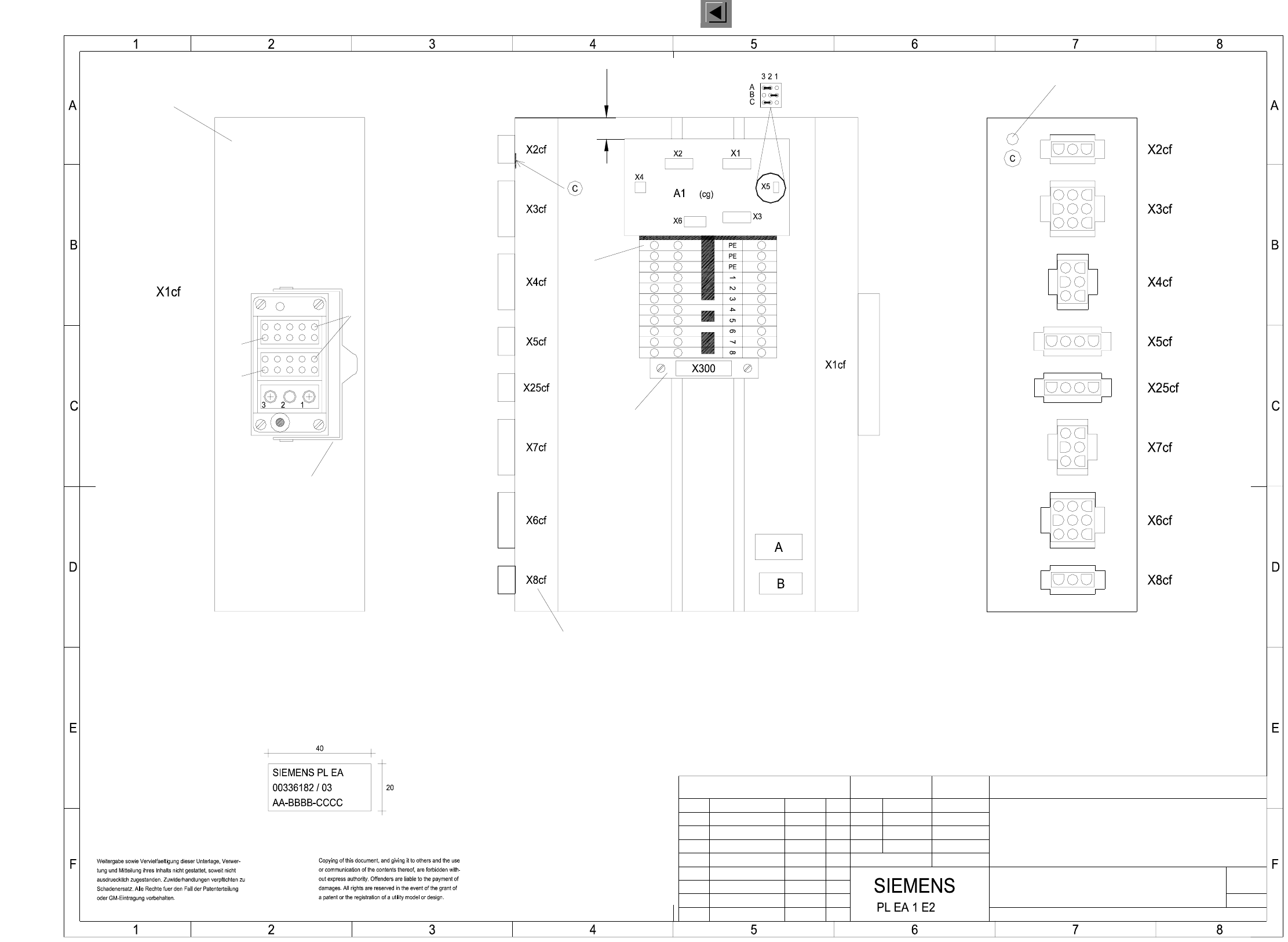
00336182-030103TD3 Distributor, sector 3
Status Modified Date Name
Author
Check.
Stand.
Date Name
(Drawing number)
Main no.
Sheet
Sh.
CAN bus coupler for comp. table 3
Jumper configuration
03.
01.
Tek
Tek
Tek
10.04.00
21.04.99
21.04.99
Hoffmann14.01.1998
03.
1
A3
1
00336182-030103TD3
10.04.00
7
FSUAUSESFS
SMD Placement System SIPLACE HS50
Distributor, sector 3
Ground hole
A: Identification label Assembly inscription acc. to VA-F-510-001
Font size 2.5 mm, material Scotchal 3698-E (color A1 RAL 9006)
BBBB = Date (year/month/day) acc. To SN 01007
CCCC = Manufacturer/location of plant acc. to SN 37040
Identification: testing engineer, month, year
C: PE label (gn/ye)
B: Inspection label
AA = Numerals
will be connected with an additional yellow/green jumper.
The ’PE terminal block’ and the ( 1 2 3 ... ) terminals
and 2 grey 3-pole terminal blocks with 2 yellow/green jumpers.
’PE terminal block’ made of a yellow/green 3-pole terminal block
Document status
Product status
Function status
font size 4 mm
Plug inscription on edge,
The following labels have to be applied:
* Please note!
Module A
Module B
Pin12
Pin12
Bracket
Pin1
Part 001
Part 002
gn/ye
(Pins 1 and 3 are wired)
Pneumatic module