SIPLACE HS50 电路图 - 第107页
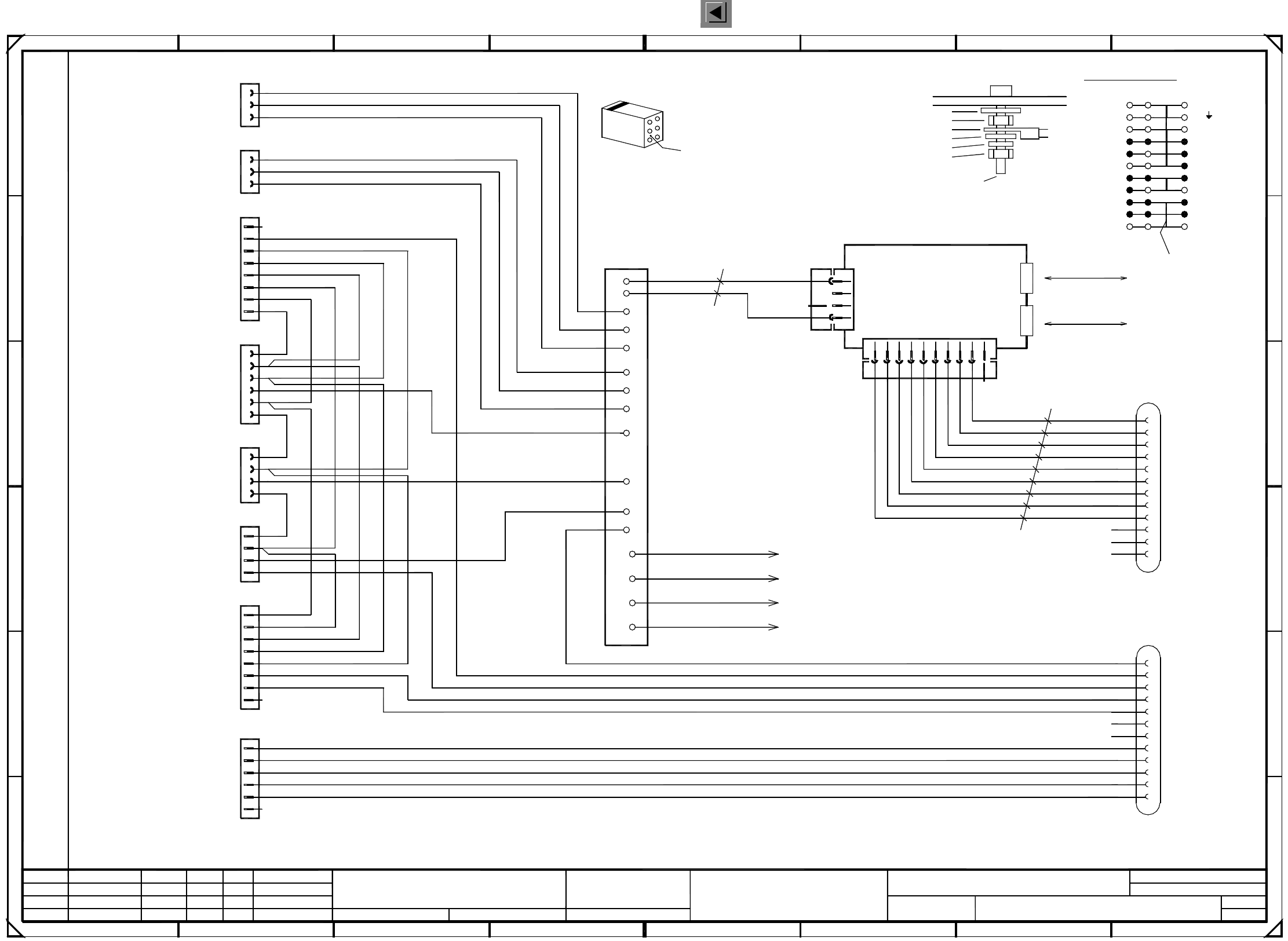
2 Circuit Diagr ams 107 I 0033618 2-030 103TD3 D istributo r , secto r 3 Sta tus Mo dified Date Name Autho r Check. Sta nd. Date Name (Dr awin g number) Main no. Sheet Sh. CAN bus coupler for c omp. table 3 Jump er confi…
2 Circuit Diagrams 106
I
00336182-030102LD3 Distributor, sector 3
1
X300 terminals overview
CAN bus
X3cg
X2cg
F
B
500kbps
32
1
4
5
6
7
ab c
CAN bus
500kbps
+5V
B10
B11
B12
B2
00332557 (cg)
2
X4cg
Locking clip plug:
key
key
B module
X1cf
B1
B6
B8
CANH
CAN_INT
CANL
C
D
E
10
2
3
A1 CAN-bus coupler
X3cg and X4cg
3
2
8
78
A
X300
To cover
gnye
PE
GND
B7
B9
00336790
X1cg
X3cg
4
3
1
D
C
GND
B5
B4
B3
gnye
To distributor sheet
00336789
Ground connection :
Contact washer
M5 hexagon nut, DIN 439
Annular cable lug
M5 washer, DIN 125
5
B
gnye
To Harting plug housing (from X1)
E
+5V
+24V
Bridge
0.56mm² / bk
0.56mm² / bk
6
5
M5 split washer, DIN 7980
M5x16 fillister head screw, DIN 912
M5 hexagon nut, DIN 439
Distributor sheet
4
SMD Placement System SIPLACE HS50
GND
+5V
A
X4cg
X7cf
X3cf
Hood3
All control lines: 1.00mm² / black
Cable ties are used to form the cable harness !
+24V
X25cf
CompFlap3
CAN_RESET
F
67
PE
PE
8
00336787gnye
To machine frame
00336788
+24V
+24V
1P34V
P8V
N8V/34V
GND
+5V
+24V
GND
+5V
+24V
X5cf
X2cf
X8cf
X4cf
X6cf
GND
1P34V
P8V
N8V/34V
A module
X1cf
A7
A10
A11
A12
A5
A3
A8
A4
A6
A9
A1
A2
02.
Function stat.
Product stat.
Document stat.
24.03.99
08.09.99
11.12.1997
Hoffmann
Distributor, sector 3
00336182-030102LD3
1
24.03.99
Voltages ring circuit
Sec2<>Sec3
Voltages ring circuit
Sec3<>Sec4
Infeed
Socket 3, peripheral modules
StartStopOutputRight
Emerg.StopPCBOutput
Safety ring circuit
Sec2<>Sec3
Safety ring circuit
Sec3<>Sec4
Cable
1
Tek
Tek
Tek
03.
01.
9
910
1
2
3
4
1
4
that the numerical sequence of a locking clip plug
Please note that ...
must be as viewed from the rear side of the casing.
7b
7c
3c
PE
PE
PE
PE
7
8
8
GROUND
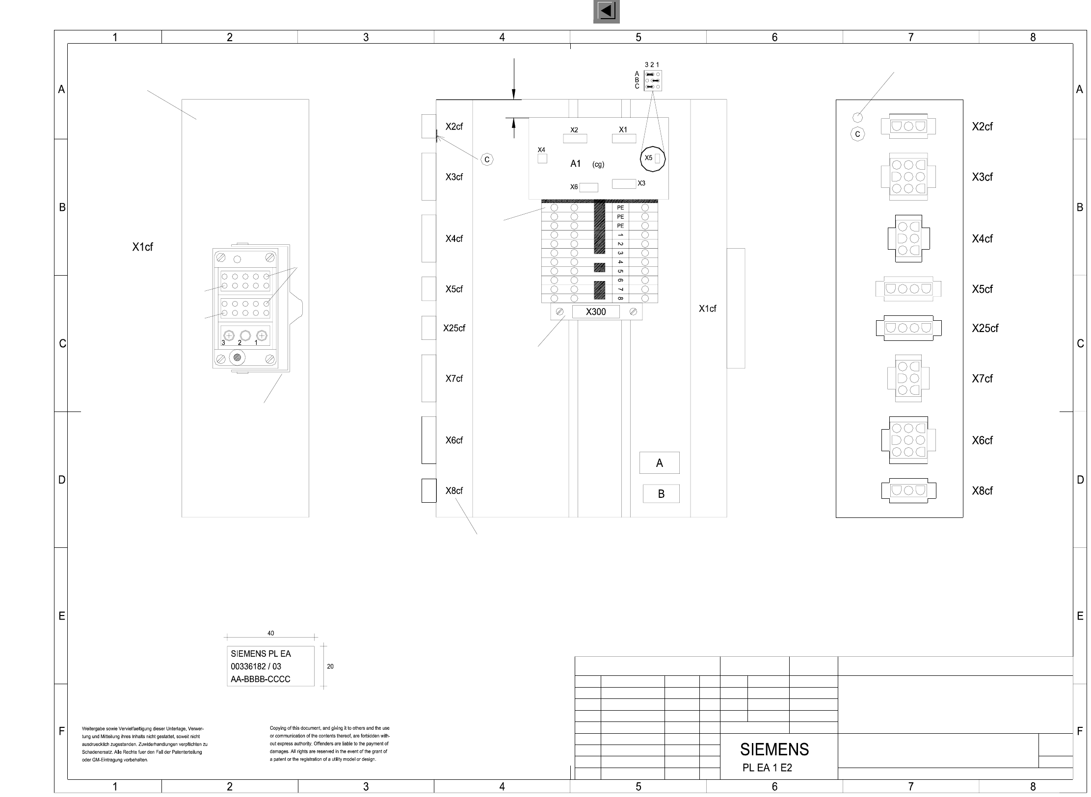
PL EA1 E2
7a
4
5
6
6
7
1
5
14
31
2
2
3
3
1
5
4
2
8 / 9
3
5
4
6
2a
4a
6a
7
1
2
3
1
2
3
6
3
6
4b
1a
2c
4c
6c
4
5
3
4
6
7
5
4
1
2
2
4
1
3
2
8 / 9
2
1
3
1
2
Spare
S_CompFlap
S_StopButton
L_End
S_Emerg.StopButton
S_StartButton
S_hood
S_CompEnd
L_Begin
S_StartButton
S_Emerg.StopButton
S_StopButton
L_End
L_Begin
S_hood
L_End
L_Begin
S_CompFlap
L_End
S_StopButton
S_CompFlap
S_Emerg.StopButton
S_StartButton
S_hood
L_End
S_CompEnd
Spare
PCC31
PCC32
Spare
Address bit 0
GND_Address
Address bit 1
Spare
Spare
Spare
S_Begin
L_Begin
L_End
S_End
Spare
Spare
PCC31
PCC32
ModifiedStatus Stand.Date Name Orig. Creat. byCreat. f.
Author
Check.
Date
Sheet
Sh.
3
5
2
4
6
1
=
SIEMENS AG
+
2 Circuit Diagrams 107
I
00336182-030103TD3 Distributor, sector 3
Status Modified Date Name
Author
Check.
Stand.
Date Name
(Drawing number)
Main no.
Sheet
Sh.
CAN bus coupler for comp. table 3
Jumper configuration
03.
01.
Tek
Tek
Tek
10.04.00
21.04.99
21.04.99
Hoffmann14.01.1998
03.
1
A3
1
00336182-030103TD3
10.04.00
7
FSUAUSESFS
SMD Placement System SIPLACE HS50
Distributor, sector 3
Ground hole
A: Identification label Assembly inscription acc. to VA-F-510-001
Font size 2.5 mm, material Scotchal 3698-E (color A1 RAL 9006)
BBBB = Date (year/month/day) acc. To SN 01007
CCCC = Manufacturer/location of plant acc. to SN 37040
Identification: testing engineer, month, year
C: PE label (gn/ye)
B: Inspection label
AA = Numerals
will be connected with an additional yellow/green jumper.
The ’PE terminal block’ and the ( 1 2 3 ... ) terminals
and 2 grey 3-pole terminal blocks with 2 yellow/green jumpers.
’PE terminal block’ made of a yellow/green 3-pole terminal block
Document status
Product status
Function status
font size 4 mm
Plug inscription on edge,
The following labels have to be applied:
* Please note!
Module A
Module B
Pin12
Pin12
Bracket
Pin1
Part 001
Part 002
gn/ye
(Pins 1 and 3 are wired)
Pneumatic module
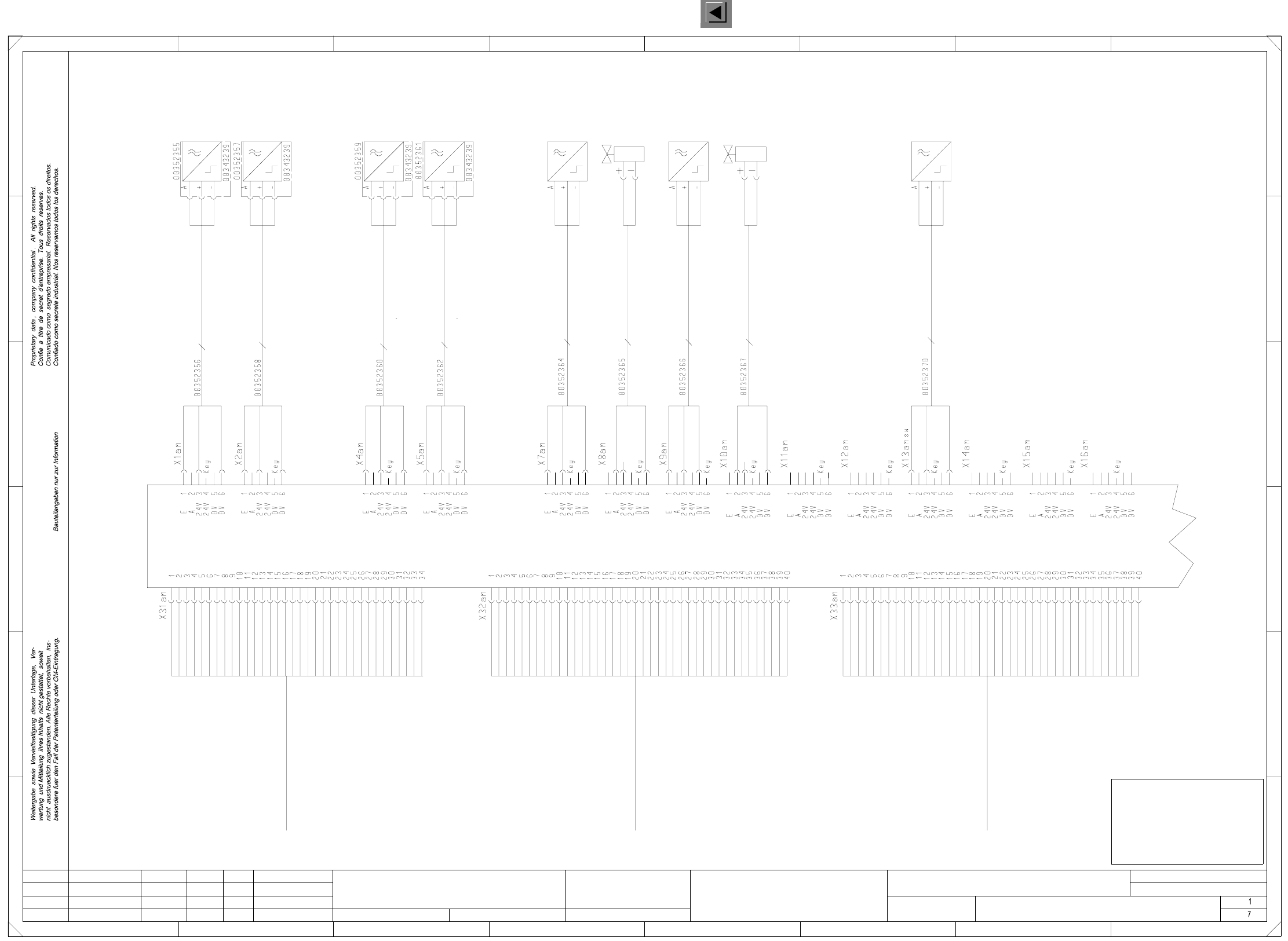
3 OPTIONS Circuit Diagrams 108
I
3
OPTIONS
Circuit
Diagrams
00119025-020101LD3 Dual conveyor, stationary side on the right,
wiring for conveyor 1, TSP200 (Sh. 1 of 7)
=
SIEMENS AG
+
FOR INFORMATION ONLY
This document will not
be replaced when
modifications are made!
Conversion board: Conveyor 1 am / ao
76
C
5
E
34 76
43
B
D
C
E
Valve
Stopper
2 x 0.25mm²
Placement section 2
Cable: stopper valve
(Conveyor 1)
Placement section 2
Stopper
Valve
(Conveyor 1)
Stopper
Prox. switch
(Conveyor 1)
Placement section 1
(Conveyor 1)
Prox. switch stopper
Placement section 1 retracted
3 x 0.14mm²
Placement section 2 retracted
3 x 0.14mm²
Prox. switch Stopper
(Conveyor 1)
(Conveyor 1)
Prox. switch
Placement section 2
Stopper
bk
bn
bl
bk
bn
bl
bl
bk
bn
bk
bn
bl
bk
bn
bl
bn
bk
bl
bk
bn
bk
bl
bl
bn
Lifting table 2
Prox. switch
top
(Conveyor 1)
Prox. switch
Lifting table 2
(Conveyor 1)
bottom
Prox. switch 2 top
(Conveyor 1)
3 x 0.14mm²
(Conveyor 1)
Prox. switch 2 bottom
3 x 0.14mm²
Prox. switch 1 bottom
3 x 0.14mm²
(Conveyor 1)
(Conveyor 1)
Prox. switch 1 top
3 x 0.14mm²
bottom
(Conveyor 1)
Lifting table 1
Prox. switch
Prox. switch
Lifting table 1
(Conveyor 1)
top
Stand.Status DateModified Name Orig. Repl. f. Replaced by
Check.
Date
Author
Sheet
Sh.
(00349302 or 00353442) (00349302 or 00353442) (00349302 or(00349302 or
00353442)
TSP200
N.u.
N.u.
N.u.
N.u.
Sonar prox. switch, excess length PCB (option)
00348267
to X11ao:2
to X11ao:6
to X10ao:6
to X10ao:2
to X8ao:2
to X8ao:6
to X9ao:6
to X9ao:2
to X7ao:6
to X7ao:2
to X3ao:2
to X3ao:3
to X3ao:5
to X3ao:6
to X3ao:7
to X3ao:8
to X3ao:10
to X3ao:4
to X15ao:2
to X14ao:2
to X23ao:2
to X22ao:2
to X21ao:2
to X20ao:2
to X19ao:2
to X13am:1
to X18ao:2
to X17ao:2
to X16ao:2
to X35am:4
to X13ao:2
to X34am:2
to X12am:2
to X11am:1
to X16am:1
to X10am:2
to X9am:1
to X8am:2
to X7am:1
to X4am:1
to X5am:1
to X1am:1
to X2am:1
to X12ao:2
to X35am:2
to X34am:11
to X34am:9
to X34am:8
to X34am:7
to X34am:6
to X34am:4
to X35am:11
to X35am:9
to X35am:8
to X35am:7
to X35am:6
Motor + EB
Motor - EB
Motor - BB1
Motor + BB2
Motor - BB2
Motor - ZB
Motor + ZB
Motor - AB
Motor + AB
Motor + BB1
Motor A - BV
Motor B - BV
Motor B - BV
Motor A - BV
LS AB (res.)
LS ZB (res.)
LS EB (res.)
Bero BV
SB BB2
SB BB1
+ 24 V
+ 24 V
GND
GND
SB EB
SB AB
SB ZB
ESCH BRA
GND
+ 24 V
A3 (Opt.)
A2 (Opt.)
A1 (Opt.)
E6 (Opt.)
E5 (Opt.)
E4 (Opt.)
E3 (Opt.)
E2 (Opt.)
E1 (Opt.)
SB UELP
Bero ST BB2
Bero ST BB1
Bero HT 2 u
Bero HT 2 o
Bero HT 1 u
Bero HT 1 o
ESCH BRZ
A3 (Opt.)
A2 (Opt.)
A1 (Opt.)
E6 (Opt.)
E5 (Opt.)
E4 (Opt.)
E3 (Opt.)
E2 (Opt.)
E1 (Opt.)
GND
VCC
Lifting table 2, topHT2o
Lifting table 2, bottomHT2u
SB
UELP
ST
LS
Sonar prox. switch
Stopper
Excess length PCB
Light barrier
Lifting table 1, bottomHT1u
HT1o
BB1
AB
BRA
BV
BRZ
EB
BB2
ESCH
Abbreviations
E
A
Width narrower
Lifting table 1, top
Width adjustment
Input conveyor
Limit switch
Input
Output conveyor
Placement sector 1
Width wider
Placement sector 2
Output
SMD-Placement System Siplace HS50
Product status
Doc. status
Function status
To TSP200 conveyor control
Conveyor 1 plug X13ao
Sensor line 2 for PCB conveyor
HS50 Conveyor 1
00351933
To TSP200 conveyor control
Conveyor 1 plug X12ao
Sensor line 1 for PCB conveyor
00351932
HS50 Conveyor 1
HS50 Conveyor 1
00351931
Motor line for PCB conveyor
To TSP200 conveyor control
Conveyor 1 plug X11ao
Prox. switch position
(Conveyor 1)
3 x 0.14mm²
bl
bn
width adjustment
width adjustment
(Conveyor 1)
Position
Prox. switch
bl
bn
bk
bk
bn
bl
bk
bn
bl
bn
wh
bn
wh
bl
bn
bk
bl
bk
bn
bn
wh
bn
wh
Blind contact
Blind contact
2 x 0.25mm²
(Conveyor 1)
Cable: stopper valve
Placement section 1
(Conveyor 1)
Placement section 1
A
Dual conveyor, stationary side on the right
8
12
A
B
F
15.03.00
01
01
02
Ha
Ha
Ha
5
2
F
D
1
8
PL EA1 E
00119025-020101LD3
Wiring (conveyor 1)
#
Haas
15.03.00
15.03.00
15.03.00