SIPLACE HS50 电路图 - 第137页
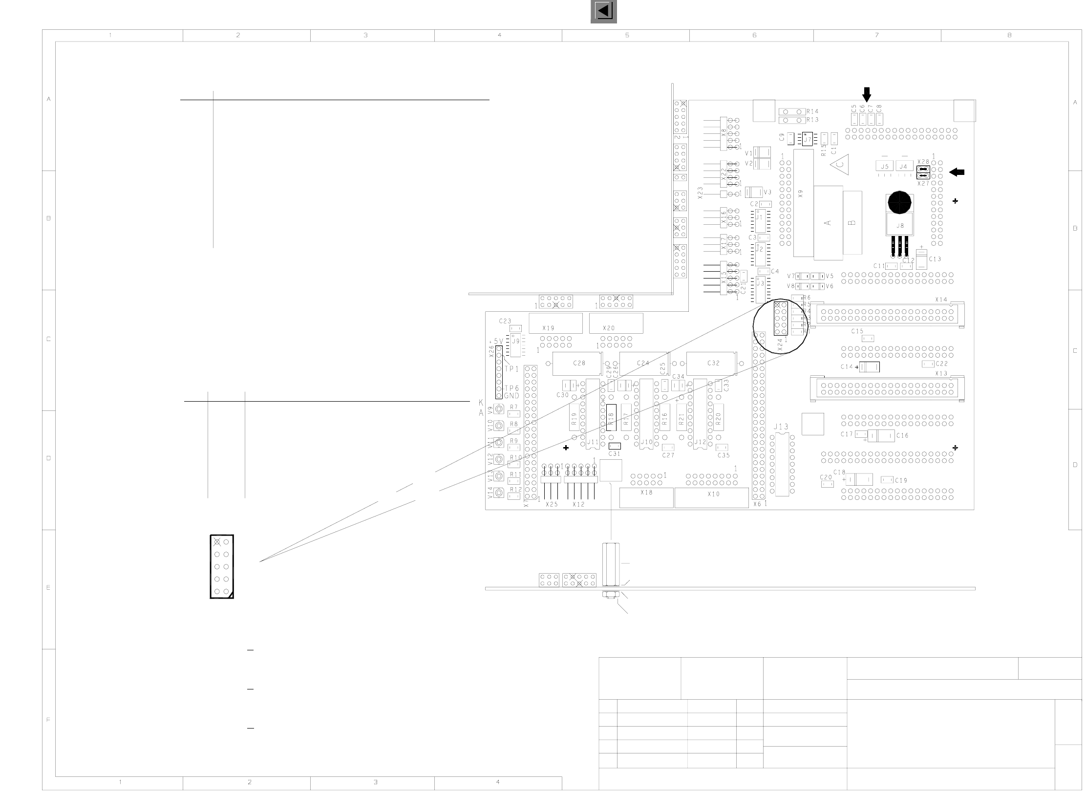
4 Printed Circui t Boards 137 I 0033145 1-020 201ND 3 826 board, C50 hea d boar d (Sh. 2 of 2) 02 01 26.03.97 20.07. 97 KL KL ATD T D MCH 2 SIEMENS A G 26.03. 97 Klose 00331451-020201ND3 Main board C50 head board 826 boa…
4 Printed Circuit Boards 136
I
00331451-020201ND3 826 board, C50 head board (Sh. 1 of 2)
must be jumpered.
C&P-head: light barrier, Z-axis upLZOSV9
V14
V13
LSVA
LSVZ
V11
V12
V10
LSZD
LSOI
LZUS
C&P-head: light barrier swiveling in of turning station
C&P-head: light barrier vacuum/switching forced air in reject station
C&P-head: vacuum/switching forced air in placement circuit
P&P-head: light barrier up (not relevant)
C&P-head: light barrier, Z-axis down
LED Signal
Assembly
X15
X23
X25
X24
X18
X17
X16
X22
X20
X19
X6
X10
X14
X13
X12
X8
X9
X7
Plug
10
10
X24
9
3 Track A
Removed
Track N
Track N
9
8
+ 5 V
Track B
Track B
GND
5
7
6
4
Track A
Analog GND1
2
6
2
4
8
5
1
3
7
Test connector for X-axis track signals
To X1, adapter board 00330648
To X2, adapter board 00330648
To X1 on vacuum board 00347857
To X3 on component illumination 00321469
To X7, processor board 00331452
To X6, processor board 00331452
Measurement points for step motors (DP-axis, pickup/placement circuit, reject circuit)
la
Oblique lighting
Illumination for PCB camera 00315224
Valve adjustment drive for reject circuit 00349432
Valve adjustment drive for pickup station 00321217
Valve adjustment drive for DP-station 00350382
End pos. proximity switch 2 for X-axis 00335169
End pos. proximity switch 1 for X-axis 00335170
Incremental shaft encoder, X-axis, 00343441
Motor/tachometer, DP-axis 00321218
PCB camera 00315224
01
02
04
KL
KL
KL
26.03.97
Klose
26.03.97
09.05.00
22.09.97
SIEMENS AG
ATD TD MCH 2
2
1
4-layer printed circuit board
Mounting diagram, component side
C50 head board
826 board
G32918-J0008-B001-*-0017
main board
C = ESD label
B = Inspection label
A = Identification label
00331451-020201ND3
Spring washer
Nut M3
Washer
Distance bolt, 15 mm
Please note:
C5 - C8 not fitted
X27 and X28
Please note:
11
Stat. Modified Date Name
Date
Name
Sheet
Sh.
Scale 1:1
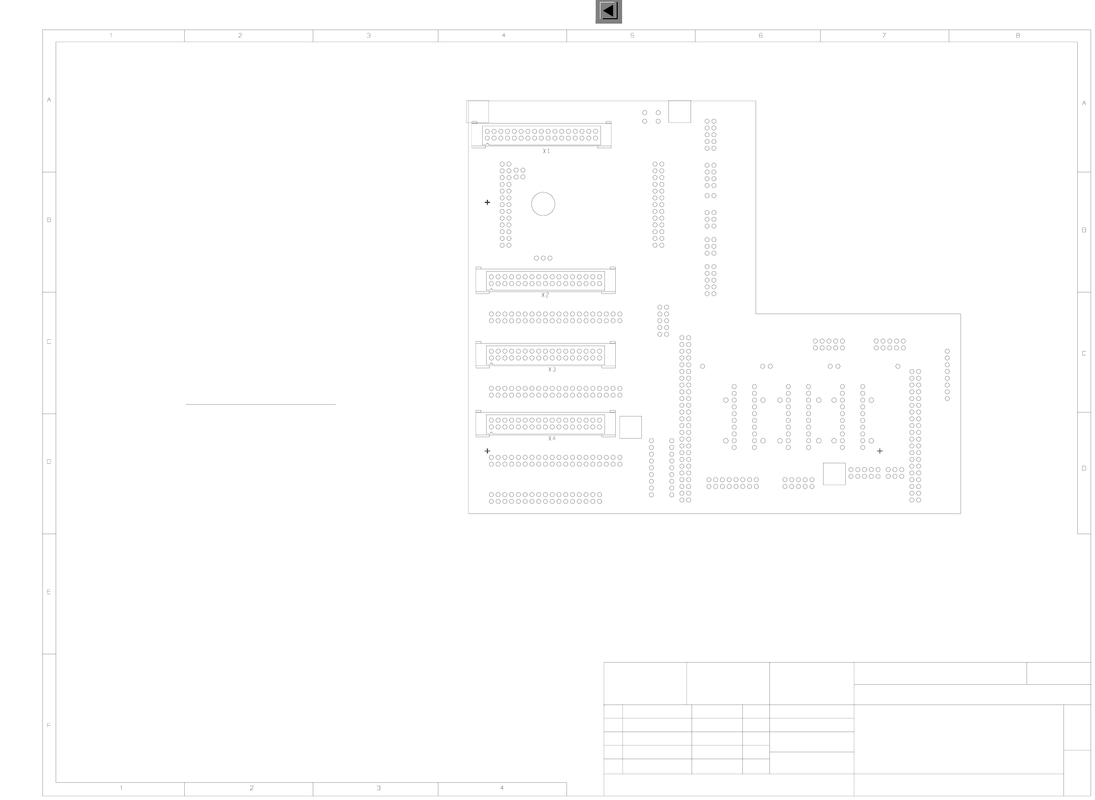
4 Printed Circuit Boards 137
I
00331451-020201ND3 826 board, C50 head board (Sh. 2 of 2)
02
01 26.03.97
20.07.97
KL
KL
ATD TD MCH 2
SIEMENS AG
26.03.97
Klose
00331451-020201ND3
Main board
C50 head board
826 board
G32918-J0008-B001-*-0017
Mounting diagram, solder side
4-layer printed circuit board
2
2
Stat. Modified Date Name
Date
Name
Scale 1:1
Sheet
Sh.
X1
X3
X4
X2
AssemblyPlug
To X1 of gantry distributor 00335413
To X4 of gantry distributor 00335413
To X3 of gantry distributor 00335413
To X2 of gantry distributor 00335413
Please note: X5 will not be fitted
04 09.05.00 KL
4 Printed Circuit Boards 138
I
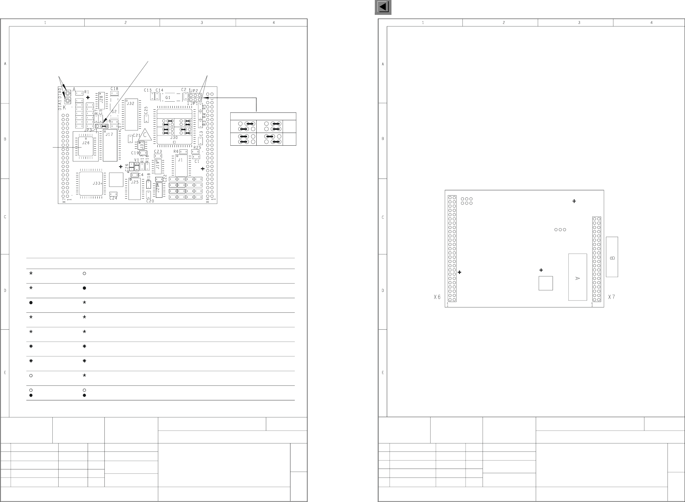
00331452-030201ND4 827 board, C51 head board, processor (Sh. 1 of 2)
00331452-030201ND4 827 board, C51 head board, processor (Sh. 2 of 2)
A = identification label
B = inspection label on the outside of X7
G32918-J0008-B002-*-0017
4-layer printed circuit board
Mounting diagram, solder side
827 board
C51 head board
processor
00331452-030201ND4
2-
ATD TD MCH 2
SIEMENS AG
26.03.97
Klose
26.03.97 KL01
Stat. Modified Date Name
Date
Name
Scale 1:1
Sheet
- - - - - - -
03
- - - - - - -
26.04.00 KL
03
02
01 26.03.97
23.09.97
26.04.00
KL
KL
KL
ATD TD MCH 2
SIEMENS AG
15.01.98
Klose
00331452-030201ND4
processor
C51 head board
827 board
G32918-J0008-B002-*-0017
Mounting diagram, component side
4-layer printed circuit board
1+
Fit J26 on a socket
C = ESD label
R12 C10 C9 R11
R2
JP1 and JP2 are used for coding the gantry.
Jumper pin 3 on JP2 and JP3.
Please note:
R15 C13 C8 R10
R13 C11 C6 R8
R14 C12 C7 R9
R19 C27
R20 C28
R24 C32
R23 C31
R22 C30
R21 C29
Stat. Modified Date Name
Date
Name
Scale 1:1
Sheet
DIA0 and DIA1 are LEDs for head board diagnosis
P3
P1 P2
P4
P2
P4
P3
P1
JP2
JP1
JP2
JP1
Gantry Coding
Gantry Coding
DIA0 DIA1
OK
Status
-
-
or steady light
synchronously
alternately
Flashing rapidly
synchronously
Flashing rapidly
alternately
Off
Off
Flashing
Steady light
Flashing
normally
Flashing
normally
Flashing
synchronously
Steady light
alternately
Flashing rapidly
synchronously
Flashing rapidly
or steady light
alternately
Flashing
Off
normally
Flashing
normally
Flashing
Flashing
Off
Remedy
is repeated successfully
Goes out automatically if transmission
or COM module of control unit
Fault in CAN bus wiring
at head board
Check power failure wiring
Check gantry address jumpers
Hardware reset
Hardware reset
at head board
otherwise processor error
Check RESET signal,
on head board
Hardware error
Transmission
Transmission
buffer of CAN bus
Firmware error
Power failure
rather than command
Head board received message,
Overflow in receive
not be sent
CAN message can
error
error