SIPLACE HS50 电路图 - 第60页
2 Circuit Diagr ams 60 I 001 19046-0201 01LD3 Single conveyo r , stationary si de on th e right , wiring, co nveyor 1, TSP20 0 (Sh. 1 of 4) SMD-Pl acement System Sip lace HS50 Prod uct s tatus Doc. statu s Func tion stat…
2 Circuit Diagrams 59
I
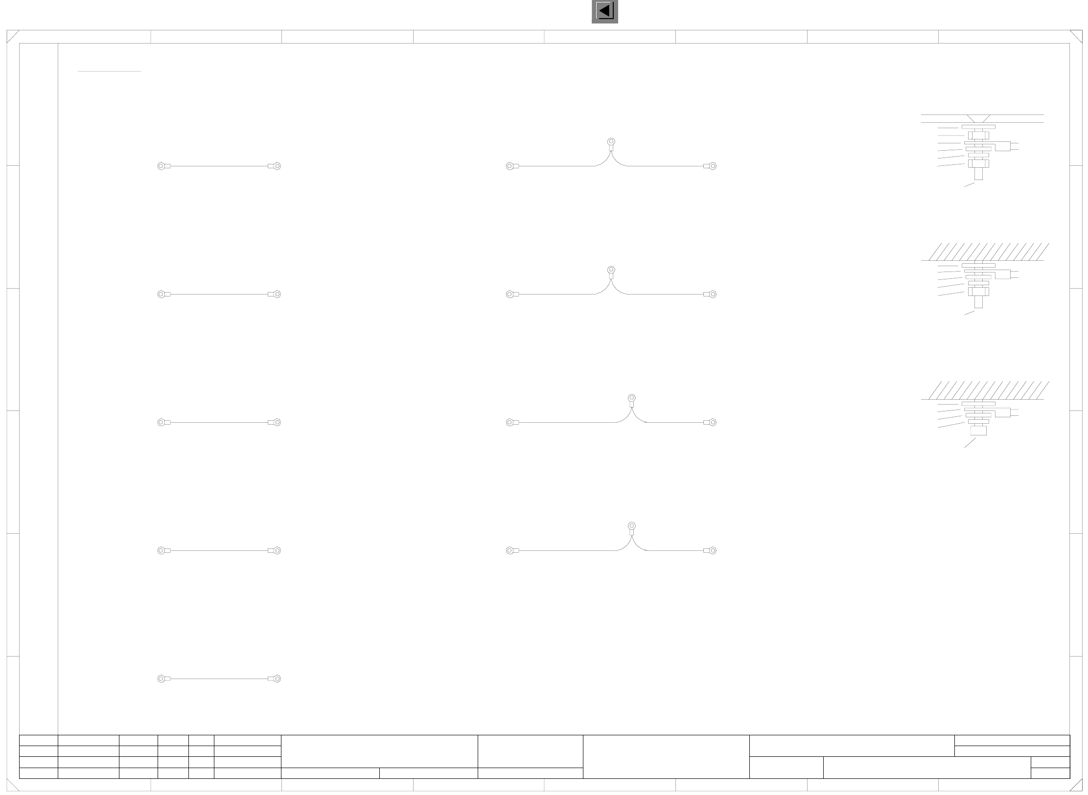
SMD placement system SIPLACE HS-50, basic module (Sh. 10 of 10)
=
SIEMENS AG
+
(M5/welding bolts)
Base
(M5/welding bolts)
Door
(M5/welding bolts)
00342101-W2
Annular cable lug
Disc, M5 DIN125
Split washer, M5 DIN7980
Fillister head screw M5x12 DIN912
Ground connection: M5 / welding bolts
Grounding, cover for gantry distributor 1 - Control elements on the left
00342079-W1
1
4
Grounding, door - control elements on the right
D
Grounding, cover for gantry distributor 2/4 ( 2x )
(M5/internal thread)
Control elements on the right
(M5/internal thread)
Machine frame
(M5/internal thread)
Machine frame
(M5/internal thread)
Cover, gantry distributor 1
(M5/counter sunk screw)
Grounding, door - control elements, lefthand side
Grounding, base, side of output conveyor ( 2x )
00342078
B
Door Control elements on the left
Split washer, M5 DIN7980
Welding bolts M5
Hexagon nut, M5 DIN439
A
Cover, gantry distributor 3
(M5/counter sunk screw)
8
D
6
F
E
7
C
E
5
A
Base
2 8
HS50 grounding
1
Ground connection: M5 / internal thread
Contact washer
00342078
Status DateModified Name Stand. Orig. Replacement for Replaced by
Author
Date
Check.
Sheet
Sh.
Door
(M5/welding bolts)
Control elements on the right
(M5/internal thread)
00342080Base
(M5/welding bolts)
Machine frame
(M5/internal thread)
00342080Base
Gantry distributor 2/4
(M5/counter sunk screw)
Cover
Ground connection: M5 / counter sunk screw
Contact washer
Hexagon nut, M5 DIN439
Annular cable lug
Disc, M5 DIN125
Split washer, M5 DIN7980
7
Grounding, base, side of input conveyor, door ( 2x )Grounding, base, side of input conveyor (2x)
00342079-W2
00342101-W1
62
Counter sunk screw M5x16 DIN965
Hexagon nut, M5 DIN439
Cover sheet
Contact washer
Annular cable lug
Disc, M5 DIN125
00342101-W1
Grounding, base, side of output conveyor Door ( 2x )
Base
(M5/internal thread)
(M5/welding bolts)
Control elements on the left
(M5/internal thread)
(M5/welding bolts)
Base
(M5/welding bolts)
Door
(M5/welding bolts)
00342244 Machine frame
(M5/internal thread)
Grounding, cover for gantry distributor 3 - Control elements on the right
34
B
01.
10.
01.
Tek
Tek
Tek
(M5/welding bolts)
Machine frame
00342079-W2
C
00342079-W1
F
35
00342101-W2
PL EA1 E2
00119050-011001LD3
SIPLACE HS50, base
Hoffmann
16.02.1998
16.03.00
16.03.00
16.02.98
Weitergabe sowie Vervielfaeltigung dieser Unterlage, Ver-
wertung und Mitteilung ihres Inhalts nicht gestattet, soweit
nicht ausdruecklich zugestanden. Alle Rechte vorbehalten, ins-
besondere fuer den Fall der Patenterteilung oder GM-Eintragung. Bauteilangaben nur zur Information
Comunicado como segredo empresarial. Reservados todos os direitos.
Confie a titre de secret d’entreprise. Tous droits reserves.
Proprietary data , company confidential . All rights reserved.
Confiado como secrete industrial. Nos reservamos todos los derechos.
10
10
SMD-Placement System Siplace HS50
Product status
Doc. status
Function status
2 Circuit Diagrams 60
I
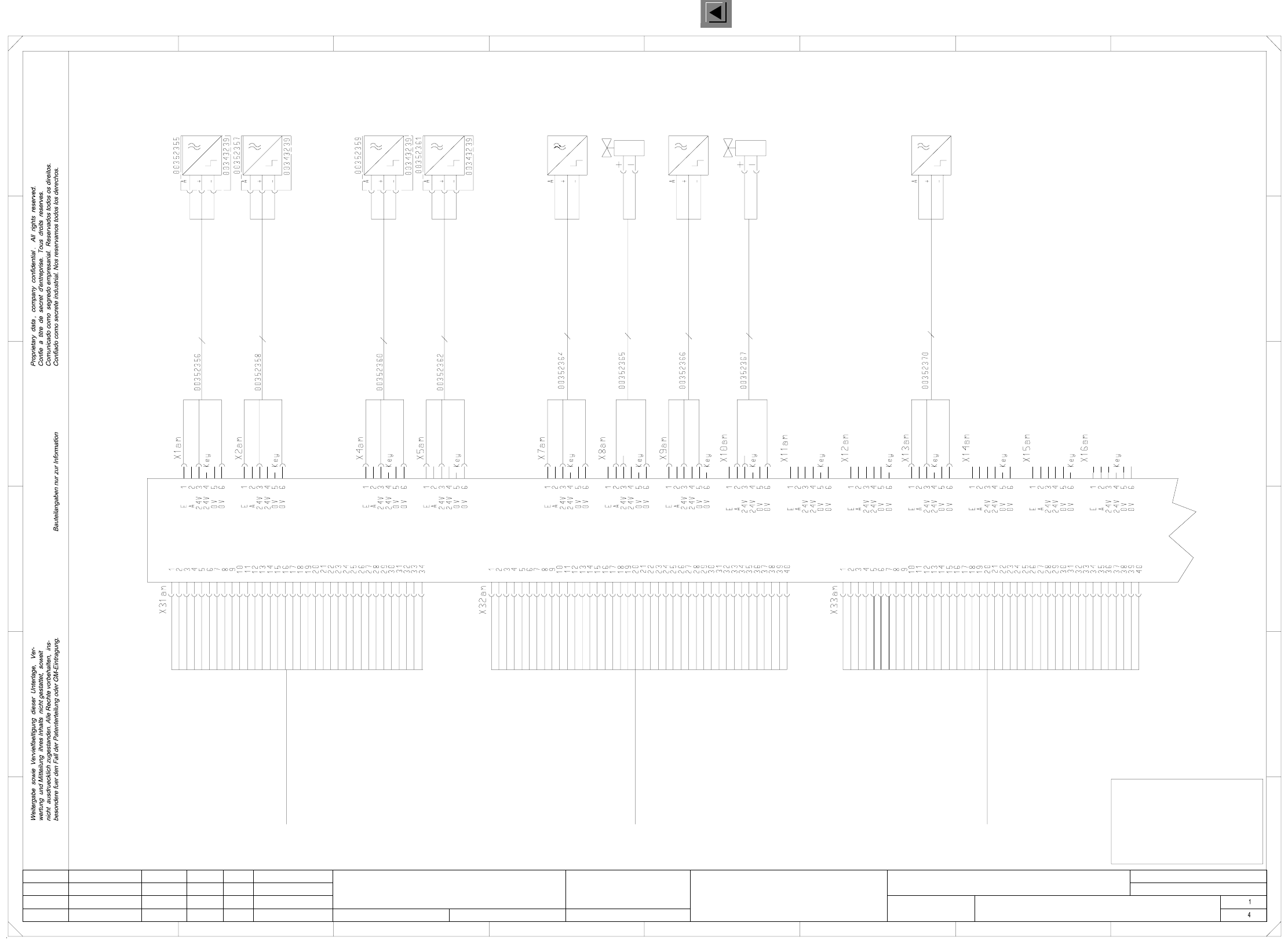
00119046-020101LD3 Single conveyor, stationary side on the right,
wiring, conveyor 1, TSP200 (Sh. 1 of 4)
SMD-Placement System Siplace HS50
Product status
Doc. status
Function status
to X22ao:2
to X23ao:2
ESCH BRA
ESCH BRZ
Bero HT 1 o
Bero HT 1 u
Bero HT 2 o
Bero HT 2 u
Bero ST BB1
Ventil ST BB1
Bero ST BB2
Ventil ST BB2
SB UELP
Bero ST UELP
Ventil ST UELP
Code 1 (Opt.)
Code 2 (Opt.)
Code 3 (Opt.)
E1 (Opt.)
E2 (Opt.)
E3 (Opt.)
E4 (Opt.)
E5 (Opt.)
E6 (Opt.)
A1 (Opt.)
A2 (Opt.)
A3 (Opt.)
Code 1 (Opt.)
Code 2 (Opt.)
Code 3 (Opt.)
E1 (Opt.)
E2 (Opt.)
E3 (Opt.)
E4 (Opt.)
E5 (Opt.)
E6 (Opt.)
A1 (Opt.)
A2 (Opt.)
A3 (Opt.)
VCC
GND
to X13ao:2
to X12ao:2
to X2am:1
to X1am:1
to X5am:1
to X4am:1
to X7am:1
to X8am:2
to X9am:1
to X10am:2
to X16am:1
to X11am:1
to X12am:2
to X34am:2
to X34am:4
to X34am:6
to X34am:7
to X34am:8
to X34am:9
to X34am:10
to X34am:11
to X34am:12
to X34am:15
to X34am:16
to X34am:18
to X35am:2
to X35am:4
to X35am:6
to X35am:7
to X35am:8
to X35am:9
to X35am:10
to X35am:11
to X35am:12
to X35am:15
to X35am:16
to X35am:18
Light barrierLS
ST
UELP
SB
Excess length PCB
Stopper
Sonar prox. switch
Abbreviations
ESCH
BB2
E
EB
BRZ
BV
BRA
AB
BB1
A
Placement sector 2
Limit switch
Input conveyor
Width adjustment
Width narrower
Width wider
Input
Placement sector 1
Output conveyor
Output
HT1o Lifting table 1, top
HT1u Lifting table 1, bottom
HT2o Lifting table 2, top
HT2u Lifting table 2, bottom
TSP200
00348267
1 634 78
1
F
234
A
Single conveyor, stationary side on the right
22.02.00
01
01
02
Ha
Ha
Ha
PL EA1 E
00119046-020101LD3
Wiring (conveyor 1)
#
Haas
22.02.00
22.02.00
22.02.00
=
SIEMENS AG
+
FOR INFORMATION ONLY
This document will not
be replaced when
modifications are made!
B
C
D
E
F
E
D
Conversion board, conveyor 1 am / ao
5678
A
C
B
52
To conveyor control TSP200 (00349302 od. 00353442)
Conveyor 1, plug X13ao
Sensor line 2 PCB conveyor
HS50 Conveyor 1
00351933
Sensor line 1 PCB conveyor
HS50 Conveyor 1
00351932
To conveyor control TSP200 (00349302 od. 00353442)
Conveyor 1, plug X12ao
To conveyor control TSP200 (00349302 od. 00353442)
Conveyor 1, plug X11ao
00351931
HS50 Conveyor 1
Motor line, PCB conveyor
Prox. switch, lift. table 1, bottom
(Conveyor 1)
3 x 0,14mm²
Prox. switch
Lift. table 1, bottom
bk
bn
bl
bl
bk
bn
bl
bk
bn
bk
bn
bl
bk
bn
bl
bk
bn
bl
bn
wh
Blind contact
bn
wh
Blind contact
bk
bn
bl
(Conveyor 1)
bl
bk
bn
bk
bn
bl
bl
bk
bn
bl
bn
bk
bn
bk
bl
(Conveyor 1)
Lift.table 1, top
Prox. switch
(Conveyor 1)
Prox. switch, lift. table 1, top
3 x 0,14mm²
(Conveyor 1)
Prox. switch, lift. table 2, bottom
Prox. switch, lift. table 2, top
(Conveyor 1)
3 x 0,14mm²
3 x 0,14mm²
(Conveyor 1)
(Conveyor 1)
Lift. table 2, bottom
Prox. switch
Lift. table 2, top
Prox. switch
Stopper valve
Placement section 1
(Conveyor 1)
Cable: stopper valve
Placement section 1
2 x 0,25mm²
(Conveyor 1)
Placement section 1, retracted
Prox. switch, stopper
(Conveyor 1)
3 x 0,14mm²
Placement section 1
Prox. switch stopper
(Conveyor 1)
Placement section 2, retracted
Prox. switch, stopper
(Conveyor 1)
3 x 0,14mm²
Placement section 2
Prox. switch stopper
(Conveyor 1)
bl
bn
bk
bn
wh
wh
bn
Placement section 2
(Conveyor 1)
Stopper valve
Cable: stopper valve
(Conveyor 1)
Placement section 2
2 x 0,25mm²
Width adjustment
(Conveyor 1)
Prox. switch position
3 x 0,14mm²
Width adjustment
Prox. switch position
(Conveyor 1)
bl
bn
bk
Status Modified Date Name
Author
Date
Stand.
Check.
Orig. Repl. f. Replaced by
Sheet
Sh.
to X7ao:2
to X7ao:6
to X9ao:2
to X9ao:6
to X8ao:6
to X8ao:2
to X10ao:2
to X10ao:6
to X11ao:6
to X11ao:2
Prox. switch for stopper, excess length PCB (option)
Valve for stopper, excess length PCB (option)
N.u.
N.u.
Sonar prox. switch, excess length PCB (option)
Motor + BB1
Motor + AB
Motor - AB
Motor + ZB
Motor - ZB
Motor - BB2
Motor + BB2
Motor - BB1
Motor - EB
Motor + EB
Motor A - BV
Motor B - BV
Motor B - BV
Motor B + BV
Motor B + BV
Motor A - BV
Motor A + BV
Motor A + BV
to X3ao:4
to X3ao:10
to X3ao:8
to X3ao:7
to X3ao:6
to X3ao:5
to X3ao:3
to X3ao:2
+ 24 V
+ 24 V
GND
GND
SB EB
SB BB1
SB ZB
SB BB2
SB AB
Bero BV
LS EB (res.)
LS BB1 (res.)
LS ZB (res.)
LS BB2 (res.)
LS AB (res.)
+ 24 V
GND
to X14ao:2
to X15ao:2
to X16ao:2
to X17ao:2
to X18ao:2
to X13am:1
to X19ao:2
to X20ao:2
to X21ao:2
2 Circuit Diagrams 61
I
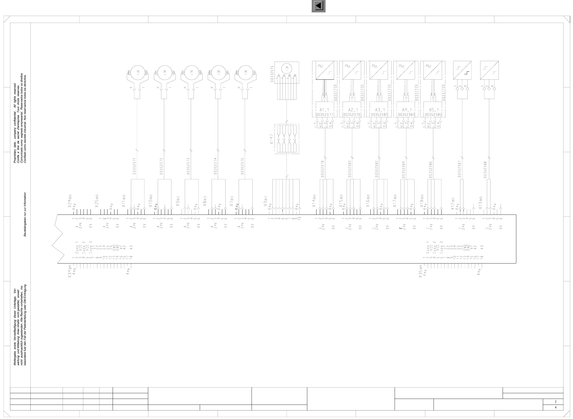
00119046-020101LD3 Single conveyor, stationary side on the right,
wiring, conveyor 1, TSP200 (Sh. 2 of 4)
C
D
Conversion board, conveyor 1 am / ao 00348267
1
01
01
02
Ha
Ha
Ha
PL EA1 E
00119046-020101LD3
Wiring (conveyor 1)
#
Haas
22.02.00
22.02.00
22.02.00
22.02.00
=
SIEMENS AG
+
Single conveyor, stationary side on the right
234 78
12
B
C
D
E
A
F
E
65
F
345678
A
B
bn
wh
2 x 0,34mm²
Input conveyor
Cable: motor
(Conveyor 1)
Motor
Input conveyor
(Conveyor 1)
Placement section 1
2 x 0,34mm²
Cable: motor
(Conveyor 1)
Motor
Placement section 1
(Conveyor 1)
Motor
(Conveyor 1)
Interm. conveyor
(Conveyor 1)
Cable: motor
Interm. conveyor
2 x 0,34mm²
Cable: motor
(Conveyor 1)
Placement section 2
2 x 0,34mm²
(Conveyor 1)
Placement section 2
Motor
2 x 0,34mm²
(Conveyor 1)
Cable: motor
Output conveyor
Motor
(Conveyor 1)
Output conveyor
bn
wh
Blind contact
Blind contact
wh
bn
Blind contact
wh
bn
Blind contact
wh
bn
Blind contact
wh
bn
wh
bn
gn
gy
ye
bl
pk
rd
bn
wh
ye
gn
gy
rd
bl
pk
or
bn
or/wh
br/wh
ye/wh
rd/wh
ye
rd
8 wires 8 wires
Motor
Width adjustment
(Conveyor 1)
bn
br/wh
or/wh
or
rd/wh
rd
ye/wh
ye
(Conveyor 1)
adjustment
Cable: motor
00352376
width Motor: width
adjustment
(Conveyor 1)
00343134
wh
bn
bk
bl
bl
bk
wh
bn
wh
bk
bn
bl
bn
bk
bl
wh
bn
bk
wh
bl
bn
wh
bn
wh
Blind contact
Blind contact
Schirm
Schirm
Schirm
Schirm
Schirm
bn
wh
wh
bn
Input conveyor
Sonar sensor
(Conveyor 1)
Sonar sensor
Placement section 1
(Conveyor 1)
Sonar sensor
Interm. conveyor
(Conveyor 1)
Sonar sensor
Output conveyor
(Conveyor 1)
Placement section 2
Sonar sensor
(Conveyor 1)
Width narrower
(Conveyor 1)
Limit switch
Limit switch
Width wider
(Conveyor 1)
Cable: sonar sensor
Input conveyor
(Conveyor 1)
4 x 0,34mm²
4 x 0,34mm²
4 x 0,34mm²
Cable: sonar sensor
(Conveyor 1)
Interm. conveyor
(Conveyor 1)
Placement section 1
Cable: sonar sensor
(Conveyor 1)
Cable: sonar sensor
Placement section 2
4 x 0,34mm²
4 x 0,34mm²
Output conveyor
(Conveyor 1)
Cable: sonar sensor
Limit switch: width narrower
(Conveyor 1)
3 x 0,25mm²
Limit switch: width wider
(Conveyor 1)
3 x 0,25mm²
Status Modified Date Name
Author
Date
Stand.
Check.
Orig. Repl. f. Replaced by
Sheet
Sh.
Valve, ceramic substrate centering 2 (option)
Valve, ceramic substrate centering 1 (option)
TSP200
(See 00119040-010101LD3, sheet 2)
(See 00119040-010101LD3, sheet 2)
SMD-Placement System Siplace HS50
Product status
Doc. status
Function status
Special design / options: placement section 1 Special design / options: placement section 2
bn
wh
bn
wh
bn
wh
wh
bn