VALID-LINE-WEB - 第8页
REAL TIME TEST EMULA TION When UUT s are part of complex systems, the A TE will be able to emulate the operating conditions by applying multiple stimuli and making multiple measurements in parallel. The iFUN is an analog…
Valid line
LEVEL II: LOW COST MODULAR ARCHITECTURE
Special to Type Test System (STTE) integrators have justified their choice based on cost
advantages potentially offered by targeting the solution on the specific end product
requirements, as opposed to the more general but more expensive General Purpose
ATE (GPATE). In trying to accomodate the multiple requirements of hundreds of LRU
that can be part of a final system, from serial to parallel digital, from LF to RF, from
Optronics to Pneumatic, the cost of instrument, routing and interfacing often exceed
budget limitations. Furthermore, the need to respond to multiple logistic environments,
Factory, Depot or even sheltered in the field, adds to the complexity, hence to the initial
and long term cost of the GPATE solution. Leaner, more agile compact and cost
controlled solutions are therefore offered by STTE, with the added attractive of in-house
possible realisation. But this is at the expense of limited, unflexible architectures. This
also generates a proliferation of different ATE. And the overall cost, if measured on the
life of the product, adding documentation, support, adaptations and re-engineering,
obsolescence, ends up to be much more than what expected.
The purpose of Seica's Low Cost Modular ATE (LCMA) is to offer the capability,
performance and flexibility of GPATE with the agility, scalability and cost control that can
make it competitive to a wide range of STTE solutions.
The CORE of the Seica's LCMA is based on Valid LF and Digital stimuli/masurement instrumentation
and routing, offering high performance and large capacity to meet parallel LRU Test Requirements.
Proprietary hardware is combined with GPIB, VXI, PXI or PCI Plug-and-Play COTS instruments as
required, for digital serial and HF LRU requirements. Signal routing architectures provide a three
dimensional way to connect both internal and external instrumentation at a glance.
For best signal integrity stimuli and responses are connected to the fixture and then to the UUT using
highperformance receivers like Virginia Panel VP12.
The system offers the ability to be fully controlled under the powerful VIVA Test Environment, to elect instead for other COTS Test Environments
(like NI TestStand, or HP VEE) or to combine the best of the two under control of SuperVIVA.
The result is a system offering performance, flexibility and capacityty of GPATE, within a scalable architcture and overal cost of ownership
competitive with STTE products. LCMA allows to create, around a CORE of proved hardware and software, a proven solution to meet AUDIO,
VIDEO, RF, OPTRONICS or PNEUMATIC LRU test requirements.
VALID PTE
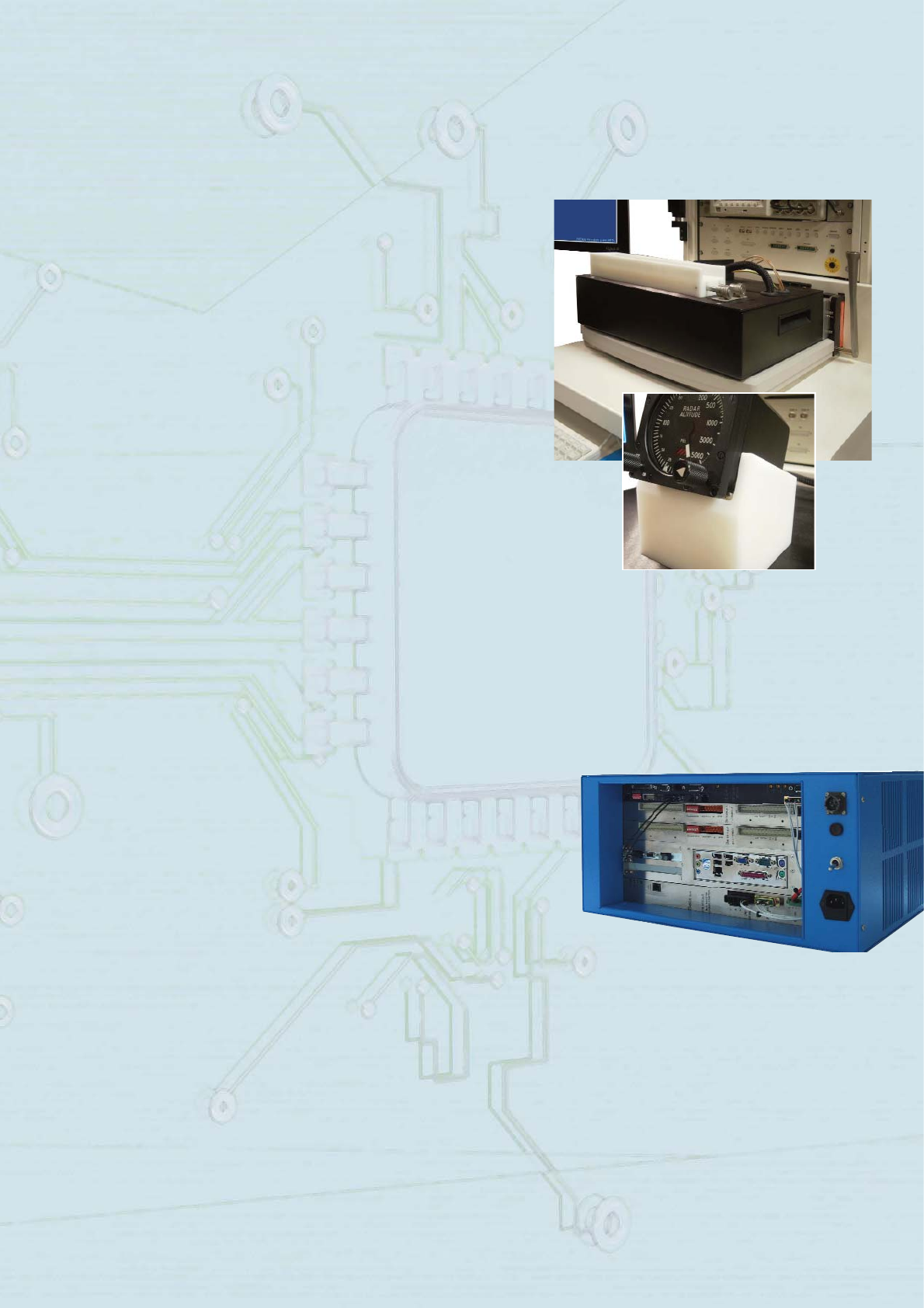
The PTE-100 Portable Test Equipment is a powerful, flexible and transportable
Intelligent Break Out Box designed to provide checkout, test and troubleshooting
for critical parts of transportation electronic systems. The PTE-100 offers test
personnel direct access to electrical signals for probing, voltage injection, isolation
checks, voltage/current and time/frequency measurements. It offers the ability to
analyze HOT and LOADED circuits, verifying missing, corrupted or valid signals.
Electrical verification activities become more efficient, repeatable and safe, thanks
to the introduction of software controlled test sequences that reduce human error
and guide diagnostic routines. Using the same advanced instrumentation of the
Valid Line, the PTE-100 can be configured to control up to 256 connections. The front panel, which can be customized to specific
applications, offers two lines of connectors (A and B) where the (normally connected) unit under test can be split and routed. The
PTE-100,inserted between the split parts, allows hot connection and disconnection operations, signal measurements and signal
injections. Each pin of the line A or B has access to an independent 4-line bus (8 lines when connected together) going to the
stimulus/measurement unit of the system (the ACL unit). Up to 256 channels can be configured, with 500V/2A carrying
voltage/current and 30VDC/200VAC/2A hot switching. Test generation and run time are controlled via the powerful QuickTest
environment, which is suited for two main modes of operation: as an instrument or as an automatic tester. The interactive display
of the stimulus/measurement/connection scenario offers menu-driven programming, direct execution, and oscilloscope
visualisation of each of the test operations. While in instrument mode, the user has full, immediate, direct control of each step by
step action; the automatic mode allows storage of the sequence of operations into a series of instructions, which can be modified
or enriched, and used for self-documentation or executed by non-skilled operators. Without limiting flexibility, the system includes
robust, customizable rules-driven procedures to avoid damaging the unit under test or the PTE-100 itself.
Housed in a 590x285x430mm chassis, and weighing approximately 20 kg,, makes it easy to transport in a carrying case. The PTE-
100 is ideally suited for Level 1 applications in commercial and military programs for avionics, ships and transportation.
LEVEL I
REAL TIME TEST EMULATION
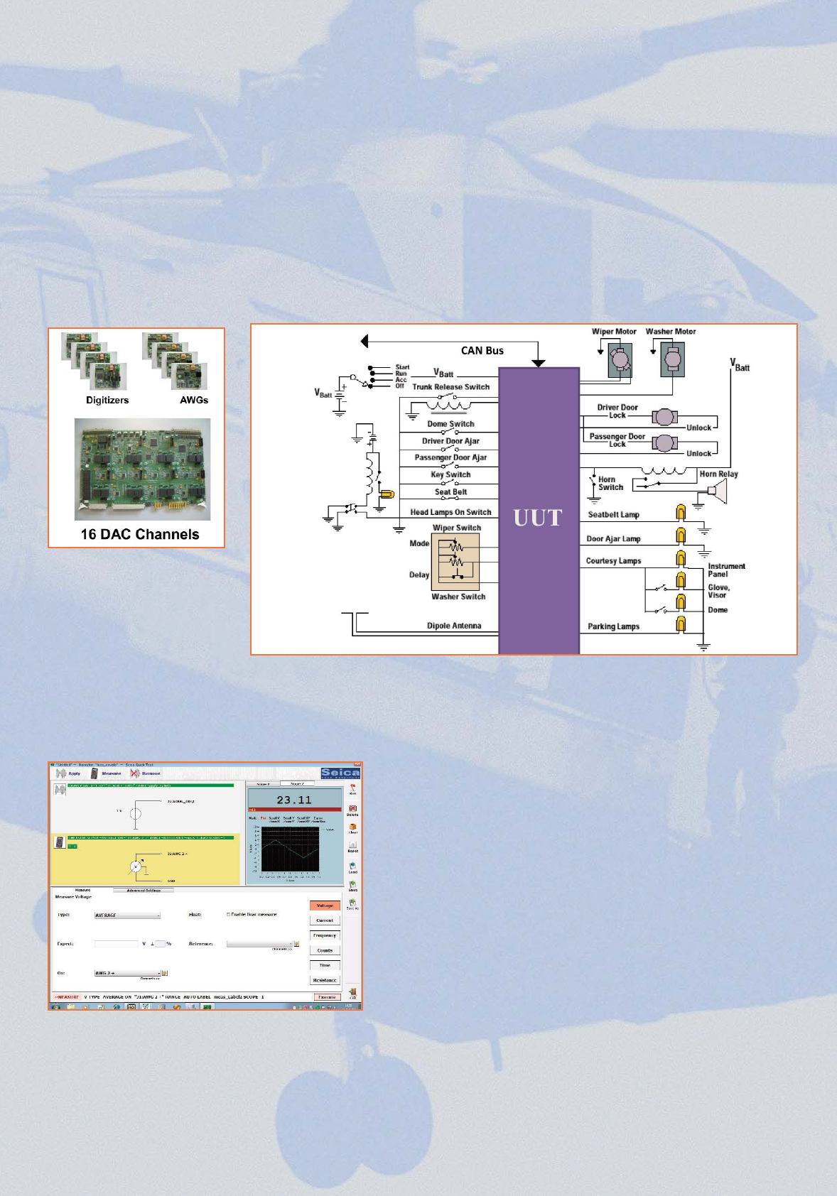
When UUTs are part of complex systems, the ATE will be able to emulate the operating conditions by applying multiple stimuli
and making multiple measurements in parallel. The iFUN is an analog test card designed to fulfil these requirements of real-
time signal generation and measurement at functional test. The card includes 16 four quadrant, grounded DC voltage
generators, programmable up to 20V with 16 bit resolution. The DC generators allow simultaneous application of independent
signals at the inputs of the UUT, to precisely reproduce discrete signals coming, for example, from sensors that are part of the
system, as frequently encountered in automotive, defence, aerospace, and industrial applications. The card can also mount up
to eight additional, independent test modules, either Arbitrary Waveform Generators (AWG) or Digitizers, in any combination,
to extend operations to a real parallel test scenario. Each AWG module has four floating voltage generators, with
programmable current limiting, and 16 bit resolution. Generation is through DDS (Direct Digital Synthesis) technique and
supported by 2M word of memory. The Digitizers allow simultaneous synchronized measurement as required by real-time test,
featuring floating mode with 16 bit resolution and up to 50MS/s sample frequency. The Valid system can hold up to four iFUN
boards, thus offering virtually unlimited parallel test capability in a matrix-free architecture.
Your Test Problem
Our iFUN Solution
Quick Test has been developed to offer engineers the ability to
combine the power of an ATE with the simplicity of a hand held
instrument. With direct graphical access to the complete path from the
instrumentation to the UUT, Quick Test allows preparing and executing
functional test scenarios in minimal time, without knowledge of the
architecture of the resources and the intricacies of language to be
used. With the test specification in one hand, the user will transfer the
information directly into the graphical environment of Quick Test and, at
a glance, get it executed and display the results.
Quick Test is easy to manipulate and to experiment with assisting the
engineer or technician in verifying test proposals.
Quick Test can be used like a Lab Instrument, for example, prior to
starting to prepare complex test procedures or as an interactive
diagnostic tool to confirm the location of a fault. The tremendous
flexibility of Quick Test makes it an ideal compliment to the Level 1
Portable Test Equipment, but also very beneficial as a tool for Level 2
STE integrators, or as a common tool between test engineers and
design engineers for the preparation of Level 3 board test programs.
Quick Test gives direct access to connections between instrumentation
and the UUT, and also supports a solid rules based control scenario,
which warns the user of potential dangerous operations to protect the
system and the UUT. Individual test operations, once created and
accepted, can be automatically converted on equivalent language
statements and stored for automatic documentation or later re-
execution.
The figure below shows the main operating screen of Quick Test.
In the upper left-hand corner, the system displays the
connection(s) being made. The upper right-hand corner serves to
have oscilloscope displays of the measurements made. The
bottom part of the screen is to modify the parameters of the
measurement; Tin the bottom line, the system directly creates the
correspondent language statement to the action graphically
executed.
QUICK TEST
Valid line
LEGACY REPLACEMENT
Seica can safely claim to have the most experience on Legacy Replacement of obsolete ATE, inclusive of the replacement solution,
the tools for TPS migration and the service to provide turn-key solutions. From the old GR179X/GR2750,Computer Automation (CA)
Marathon, and S79X test systems, to the more recent L3XX systems, Seica has successfully served customers worldwide to
migrate thousands of test programs, assuring life extension to long term defense products. There are several reasons to make
Seica the preferred partner, and the Valid Line the preferred solution, for Legacy Replacement:
- Since the start of the company in 1984, development of TPS for defense customers has been a key activity for Seica engineers.
- The Valid Line architecture is scalable to reproduce the most sophisticated digital and analog ATE configurations.
- The digital, analog, routing capabilities of the Valid Line match and exceed those of the ATE to be replaced.
- The Valid Line is committed to invest in new technologies, while at the same time retaining legacy techniques, like wide range
digital logic levels (+/- 30V),, guided probe diagnostics and fault dictionary, and analog guided probe routines, etc.
- The Valid Line can be provided with the same receiver used on the ATE to be replaced, thus accepting old fixtures without any
signal degradation.
- The Legacy Replacement environment of the Valid Line, which includes a wide number of input paths from most common
functional ATEs, is designed to fully automate TPS migration, with minimal user intervention, without loss of coverage and with
comparable, self documenting program structure.
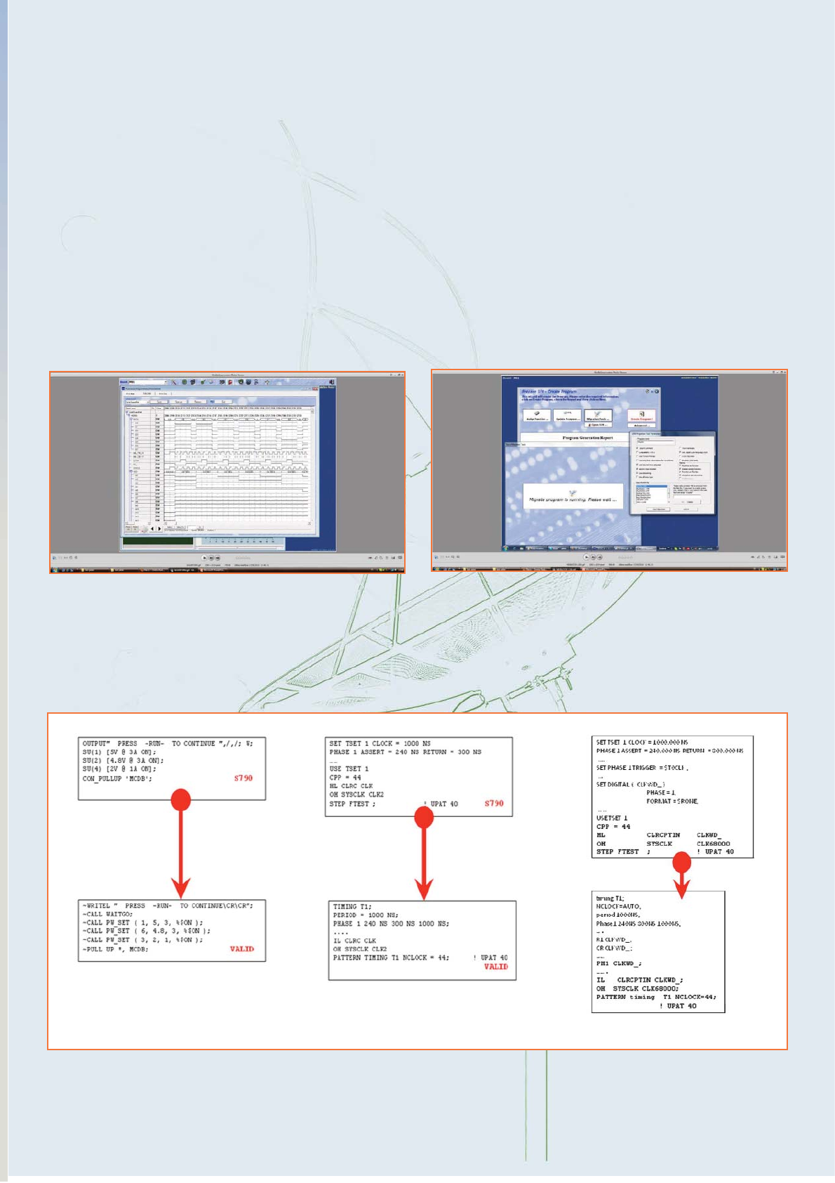
From L300 To ValidFrom S790 To Valid
The figure below shows the correspondence between the original L300 instructions and the correspondent translation for execution by the Valid
hardware. The translation environment allows selecting different formats for the Valid language so that not only the characteristics and
performance of the test action are maintained, but also the readability is optimal, should some corrections be required at verification. The
translator operates with the same accuracy to convert the diagnostic data files; the translator for L300 also covers conversion of the analog tests
and associated routing.
Legacy Replacement Environment
Legacy Replacement Logic Analyzer