00193279-03.pdf - 第20页
Retrofit / Maintenance Ins tructions SIPLACE HS -50 / HS-60 1 Retrofit / Maintenance Instructions Air filter box with more powerful fan 04/2004 US Edition 20 : Posi tion th e prepared tro ugh of the air filt er box on t …
Retrofit / Maintenance Instructions SIPLACE HS-50 / HS-60
04/2004 US Edition 1 Retrofit / Maintenance Instructions Air filter box with more powerful fan
19
1.6 Retrofit
: Switch the placement machine off at the main switch.
1
Follow the correct shut-down routine. 1
1
1
: Secure the placement machine to prevent it being switched on without authorization during the
entire retrofit.
: Visually check to make sure that both fans have stopped.
1
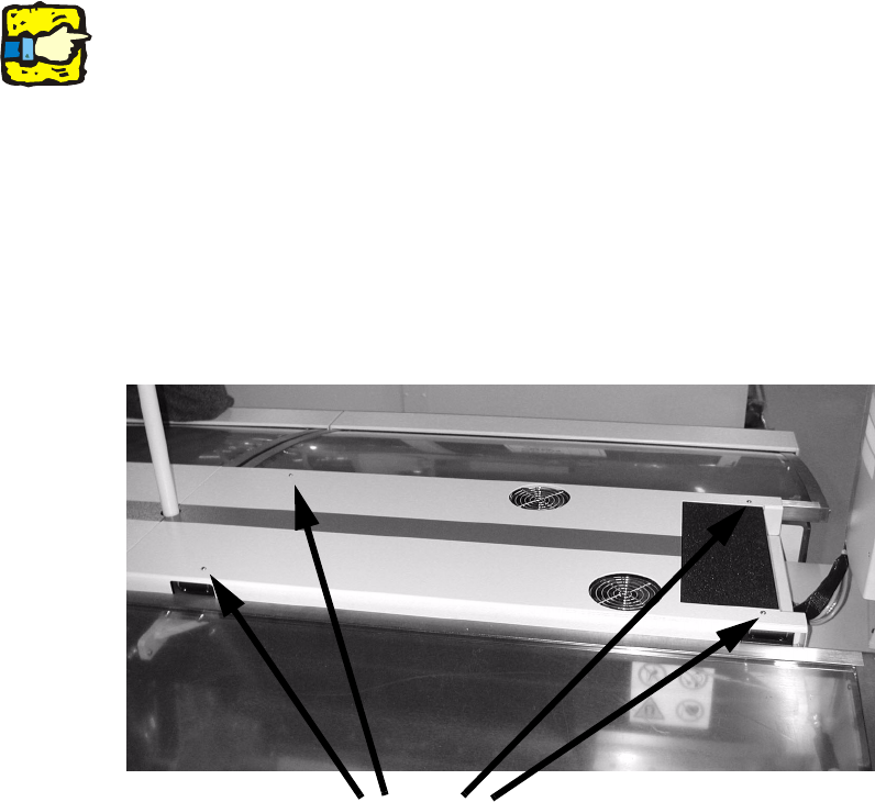
: Loosen the fixings on the gantry cover (4 tallow-drop screws M4, size 2.5 Allen key)
: Lift the gantry cover away from the machine and place the cover on a workbench.
1
1
1
1
1
1
1
Screws
Retrofit / Maintenance Instructions SIPLACE HS-50 / HS-60
1 Retrofit / Maintenance Instructions Air filter box with more powerful fan 04/2004 US Edition
20
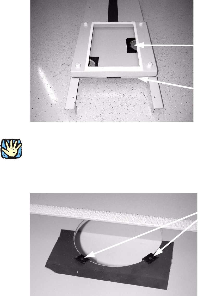
: Position the prepared trough of the air filter box on the removed gantry cover so that it is flush
with the edge of the gantry cover panel that runs across.
Make sure that both circular break-outs are covered by the air filter box.
1
1
1
Risk of injury on sharp edges. 1
1
: For each circular break-out use two 2 clamping elements (item no. 00358751-02) at an angle
of approx. 120° to one another, and thus clamp the trough of the air filter box onto the gantry
cover.
Circular break-out
Edge of metal panel
Clamping element
Retrofit / Maintenance Instructions SIPLACE HS-50 / HS-60
04/2004 US Edition 1 Retrofit / Maintenance Instructions Air filter box with more powerful fan
21
: Press the filter mat onto the Velcro strip.
1
: Repeat all the steps described above on the opposite gantry cover.
1.6.1 Replace existing 4 fans with more powerful fans
1
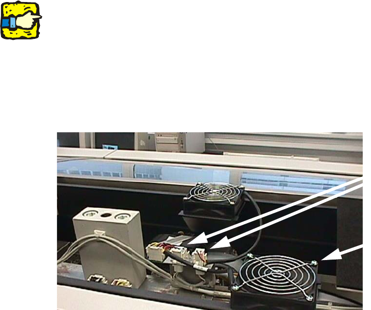
The 2 fan connectors may be arranged as required, i.e. on the left or right in the gantry area. 1
1
: Detach the plug-in connectors of the 4 fan cables (see Fig. above).
1
: Loosen the fixings for the 4 fans: each has 4 tallow-drop screws M4 (size 2.5 Allen key).
Remove the protective screens and the fans.
1
Fig. 1.6 - 1 Remove and replace four fans
: Clean the protective screen with a damp cloth.
: Insert the 4 new fans (item no. 00364951-01).
: Place the previously removed protective screens on the new fans, then fix the fans and
screens in the machine using the 4 tallow-drop screws M4 (size 2.5 Allen key).
: Attach the plug-in connectors for the 4 new fans. The connectors are locked in place.
Electrical connection
Fixing the fan