work instructions for can over lan installations.pdf - 第7页
3. Replace the label - X1pn and - X2pn with the – XCAN1 and XCAN2 in cable harness 03102233- 02 and 03102236 - 02 , then re-layout the cable harness assembly 03110437- 02 (Cable branch, CAN bus, encoder, nozzle) as per b…
Installations of CAN over LAN assemblies
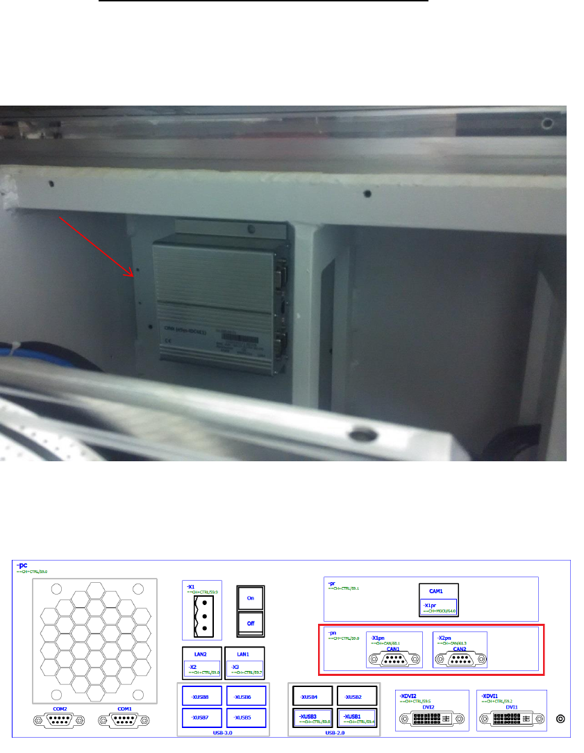
1. Install the item 03114328-01 COL bracket with the 03108598-0102 CAN Interface CINX
Module in the base machine as per below location 1 near to HMI. Make sure that all Dip
switch are in OFF position.
2. Item 03079973-02 CAN card COM168V2-PCI is removed in the Box PC 03102044-0102
(Control Computer Assembly (E-Series)) PCI slot as per below.
03108598-0102
CAN Interface CINX Module
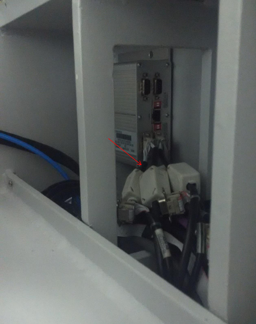
3. Replace the label -X1pn and -X2pn with the –XCAN1 and XCAN2 in cable harness 03102233-
02 and 03102236-02, then re-layout the cable harness assembly 03110437-02 (Cable branch,
CAN bus, encoder, nozzle) as per below and connect respectively to 03108598-0102 CAN
Interface CINX Module.
03110437-02
(Cable branch, CAN bus, encoder, nozzle)
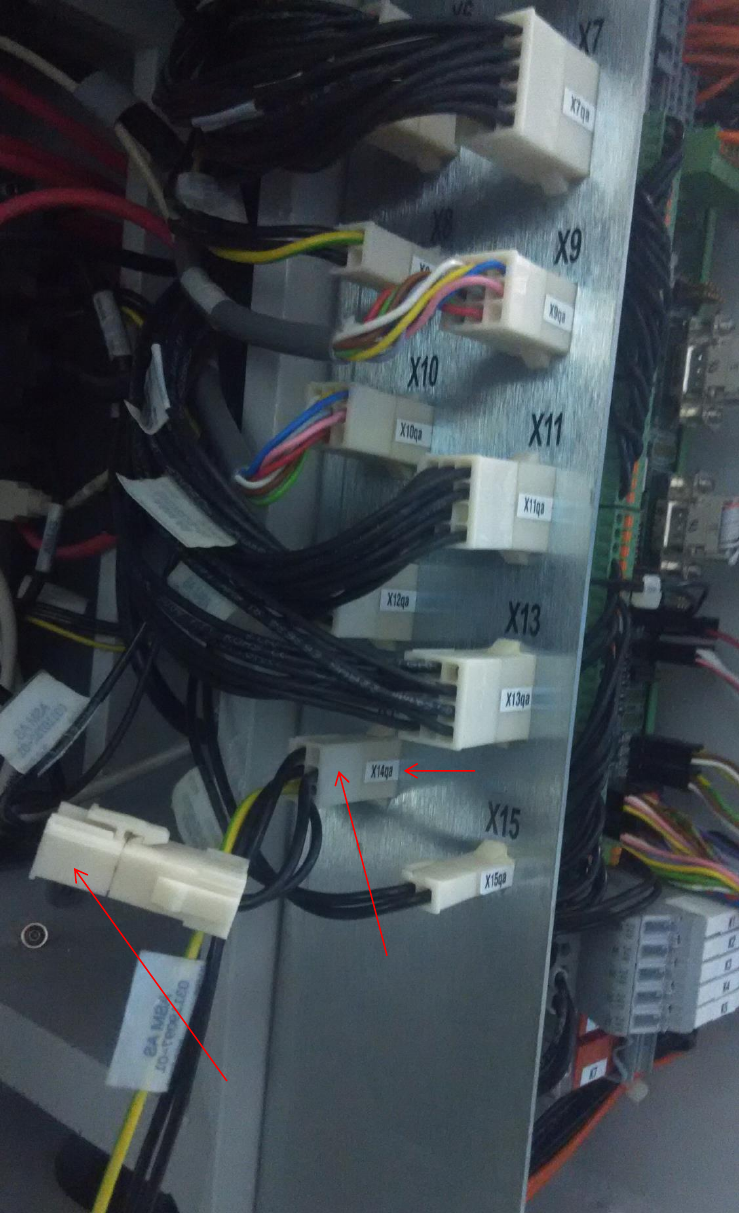
4. Adaptor cable 03119097-0201 (Cable, power f. CAN over LAN) must be installed from
03108598-0102 CAN Interface CINX Module and 03101221-01 IO Distributor Brd in
connector X14qa. Cable harness 03110732-01 is connected to the adaptor cable in
connector –X14qax.
03101221-01
IO Distributor Board
X14qa connector
03119097-0201
Cable, power f. CAN over LAN
03110732-01
Cable, vacuum pump (two loop)
X14qaX connector