ACT - Accuracy Check Tool.pdf - 第139页
ACT with SSW 7xx / User Manual 07/2017 Edition 31 4.1.1.2 Placement Program Overview for SIPLACE Pro ≥ 11.x ≤ 13.1 Station software v ersion 706.02. SP1 Hotfix 2 or 707.1.SP1 Hotfix 2 or higher. Standard ACT programs Tab…
ACT with SSW 7xx / User Manual 07/2017 Edition
30
4 Working with the ACT
4.1 Specifying the Placement and Measurement Program from
SIPLACE Pro
NOTICE
Placement program overview
The placement programs available vary according to the machine type and head/camera
configuration.
4.1.1 Selecting the Board (Placement Program)
4.1.1.1 Placement Program Overview for SIPLACE Pro < 11.x
Machine Head
Head
camera
Nozzle Placement program
X- / SX- / DX- series
X-series S / CA
C&P20x
2 x C&P20x
SST 23,
SST 41
1004 / 1014
ACT_1xC&P20
(80 x Cerampad)
ACT_2xC&P20
(2 x 80 x Cerampad)
X- / SX- /DX- series
X-series S / CA
C&P12-DLM,
CPP (C&P mode)
2 x C&P12-DLM,
2 x CPP (C&P mode)
SST 28,
SST 29,
SST 30,
SST 38
904 / 914 / 2004 /
3004
ACT_1xC&P12
(96 x Cerampad)
ACT_2xC&P12
(2 x 96 x Cerampad)
X- / SX- / DX- series
X-series S / CA
C&P6-DLM
TH-IC,
P&P-IC
SST 29,
SST 30
SST 33,
SST 36
920
518
ACT_CC02-05
(48 x CC02-05)
X- / SX- / DX- series
X-series S / CA
TH-FC,
P&P-FC
SST 25 518
ACT_CC07-500
1)
(48 x CC07-500)
X- / SX- / TX- series
X-series S / CA
CPP
(P&P mode)
SST 33 2057
ACT_CC02-05_CPP
2)
(48 x CC02-05_CPP)
Table 4-1: Assignment of machine, board, head up to SIPLACE Pro < 11.x
1)
Up to software SIPLACE Pro 11.x and the corresponding station software versions, a separate optionally available
glass component CC07-500 (with BGA structure) was used for the SST 25 camera.
As of software SIPLACE Pro 11.x with station software version 706.02.SP1 Hotfix 2 or 707.1.SP1 Hotfix 2 or higher,
the CC02-05 component (with QFP structure) is used for the SST 25 camera (Flip-Chip camera).
If you plan to measure an SST 25 with ACT, we recommend upgrading the software to the versions described below.
2)
Separate board in SIPLACE Pro for measuring the CPP head with an SST 33 stationary camera.
ACT with SSW 7xx / User Manual 07/2017 Edition
31
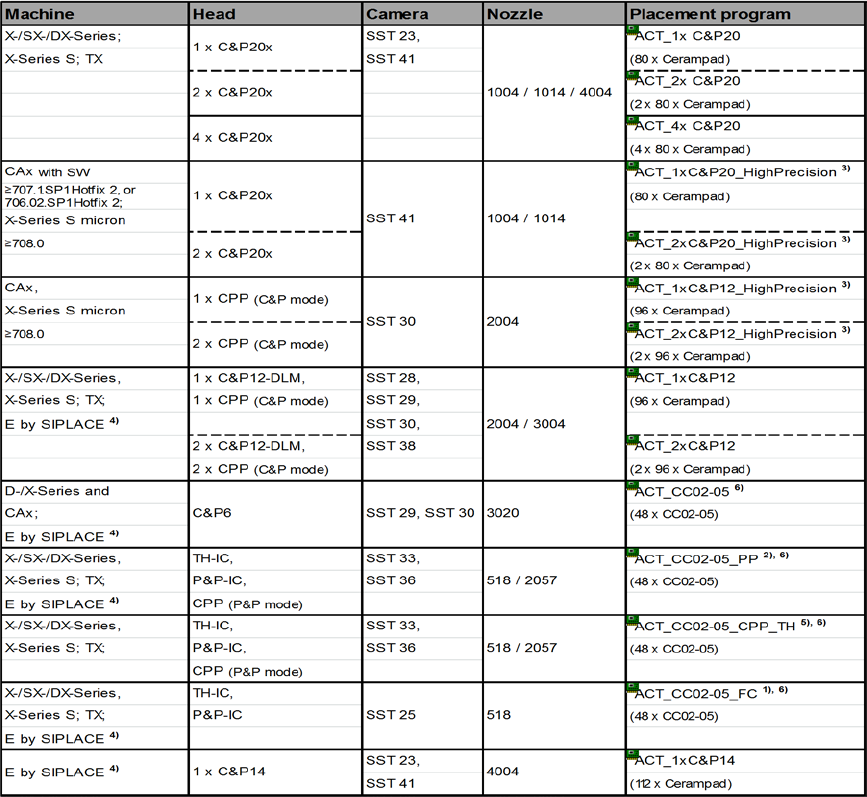
4.1.1.2 Placement Program Overview for SIPLACE Pro ≥ 11.x ≤ 13.1
Station software version 706.02.SP1 Hotfix 2 or 707.1.SP1 Hotfix 2 or higher.
Standard ACT programs
Table 4-2: Assignment of machine, board, head as of SIPLACE Pro 11.x
1)
As of software SIPLACE Pro 11.x with station software version 706.02.SP1 Hotfix 2 or 707.1.SP1 Hotfix 2 or higher,
the CC02-05 component (with QFP structure) is used for the SST 25 camera (Flip-Chip camera).
The CC07-500 glasscomponent (with QFP structure) is not supported anymore. If the CC07-500 component is already
available and still to be used for measuring the SST 25 camera, the corresponding board with its component and
component shape data and the tables can be selectively imported from the *.sipro files of the SIPLACE Pro 9 version.
This data can be obtained from the Software License Portal or via the hotline.
2)
As of software SIPLACE Pro 11.x with station software version 706.02.SP1 Hotfix 2 or 707.1.SP1 Hotfix 2 or higher.
From this version, a separate board description is available for all Pick & Place heads in which the CPP head has now
been integrated for the P&P mode.
3)
For machines requiring higher precision, such as CA machines and X S Micron, separate high precision programs with
high precision Cerampads are available for measuring the C&P20 heads. As of the software versions mentioned
above, it is possible to enable a Precision parameter in the component shape description.
4)
Machine type E by SIPLACE, as of station software version 708.0.
5)
For compatibility with older station software versions. If SIPLACE Pro has been updated without updating the station
software, the machine verification of CPP heads in P&P mode can be performed anyway with this program.
6. As of SIPLACE Pro version 11.1, board descriptions for using the Tray in Conveyor for ACT option are available, see
chapter 5.

ACT with SSW 7xx / User Manual 07/2017 Edition
32
Optional ACT programs for Tray in Conveyor as of SIPLACE Pro 11.1
Machine Head Camera Nozzle Conveyor Placement Program
X-/SX-/DX-
series,
X-series S; TX;
TH-IC,
P&P-IC,
CPP (P&P mode)
SST 33,
SST 36
518 / 2057 Single
ACT_CC02-
05_PP_ConveyorTray left
(48 x CC02-05)
Tray + ACT board connected with
adapter in single conveyor mode.
The tray is mounted to the left of the
glass plate.
X-/SX-/DX-
series,
X-series S; TX;
TH-IC,
P&P-IC,
CPP (P&P mode)
SST 33,
SST 36
518 / 2057 Single
ACT_CC02-
05_PP_ConveyorTray right
(48 x CC02-05)
Tray + ACT board connected with
adapter in single conveyor mode.
The tray is mounted to the right of the
glass plate.
X-/SX-/DX-
series,
X-series S; TX;
TH-IC,
P&P-IC,
CPP (P&P mode)
SST 25, 518 Single
ACT_CC02-
05_FC_ConveyorTray left
(48 x CC02-05)
Tray + ACT board connected with
adapter in single conveyor mode.
The tray is mounted to the left of the
glass plate.
X-/SX-/DX-
series,
X-series S; TX;
TH-IC,
P&P-IC,
CPP (P&P mode)
SST 25 518 Single
ACT_CC02-
05_FC_ConveyorTray right
(48 x CC02-05)
Tray + ACT board connected with
adapter in single conveyor mode.
The tray is mounted to the right of the
glass plate.
X-/SX-/DX-
series,
X-series S; TX;
TH-IC,
P&P-IC,
CPP (P&P mode)
All All Dual
ACT_Spacer in other Lane for
Conveyor Tray
For a job in dual lane synchronous
mode, this empty board is specified in
the lane in which the tray shall be
transported.
Table 4-3: Optional ACT programs for Tray in Conveyor as of SIPLACE Pro version 11.1