ACT - Accuracy Check Tool.pdf - 第147页
ACT with SSW 7xx / User Manual 07/2017 Edition 39 Twin Head – statistical re liability: NOTICE ► When measuring a T win Head, pay att ention to the number of placed component s per segment to ens ure the statistic al rel…
ACT with SSW 7xx / User Manual 07/2017 Edition
38
Twin Head in Placement Area 1:
For machines with Twin Head in placement area 1 (i.e. gantry 1 and / or 4), you can use the
following adapter to ensure the accessibility of segment 2 during placement on the plate. The
adapter is placed on the front of the plate to move the plate by a total of 50 mm to the rear in the
direction of the input belt.
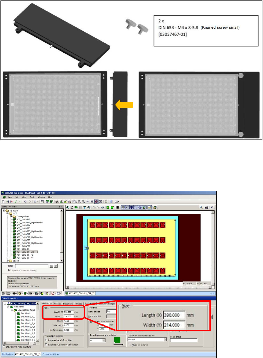
50 mm TWIN adapter [03085310-01]
Figure 4-8: 50 mm TWIN adapter
If you use the "50 mm TWIN adapter" [03085310-01] in the outmost panel, you must extend the
board by 50 mm in SIPLACE Pro Desk!
► For this, enter 390 mm length instead of 340 mm in the board description that you want to use
(ACT_CC02-05_CPP_TH).
Figure 4-9: Extending the board
ACT with SSW 7xx / User Manual 07/2017 Edition
39
Twin Head – statistical reliability:
NOTICE
► When measuring a Twin Head, pay attention to the number of placed components
per segment to ensure the statistical reliability of the measurement result.
At least 20 components per segment should be placed!
With the setup of the tray with the glass components, pickup problems may occur for some
machine types because the components cannot be reached.
► Pay attention to the tray position on the component table or in the WPC.
Variants:
► By positioning the tray on the BE table, ensure that the components can be reached in X-
direction from both segments.
As soon as the two front rows are empty:
► Stop the machine.
► Refill the components at the front.
► Set the filling level to Full again.
This also applies for the tray setup in the WPC. The components have to be refilled in the WPC
too (e.g. WPC at the SX1/2 machine) to ensure that a sufficient number of components can be
picked up by both Twin segments.
► Possibly use the Tray in Conveyor for ACT option. This ensures the accessibility in Y-
direction.
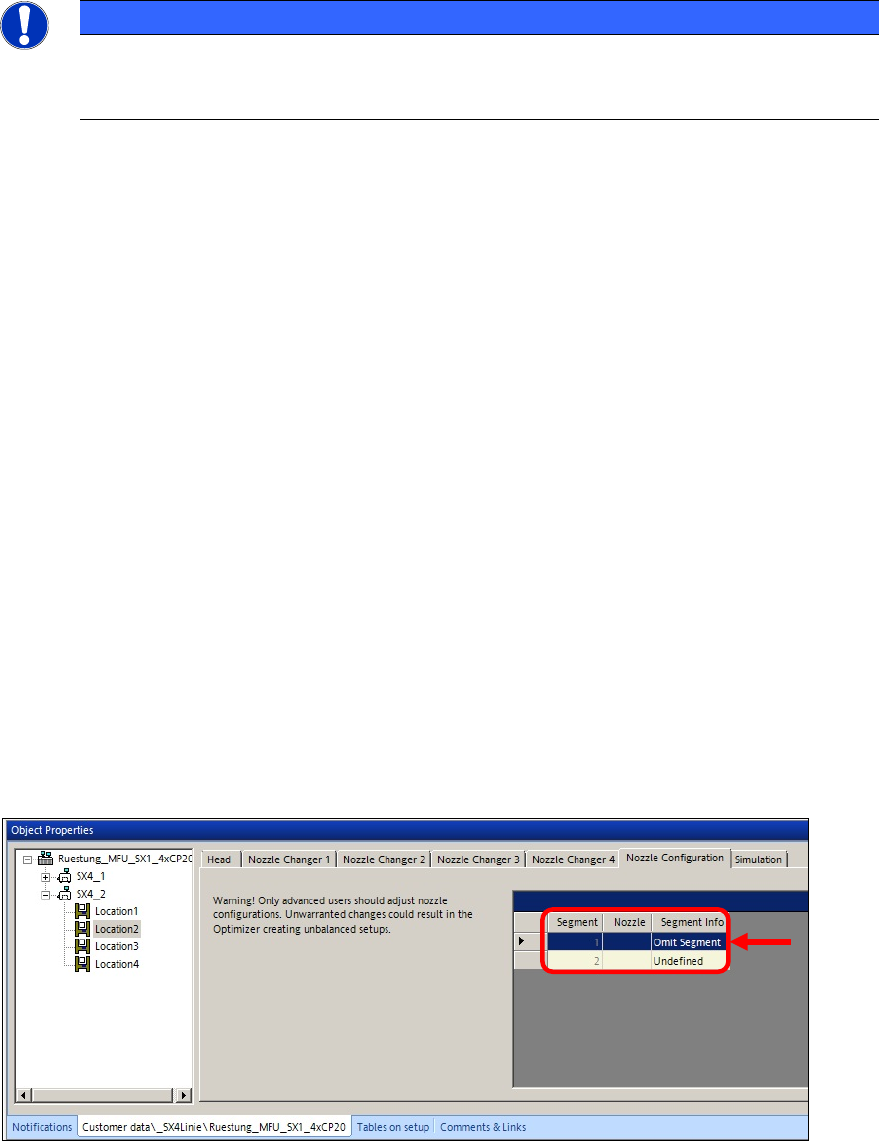
► In order to further increase the statistical reliability of the measurement result and at the same
time ensure that each segment fulfills these requirements, you can check each segment
individually.
► To do this, omit one segment at a time in the Nozzle Configuration tab of the Setup Editor
in SIPLACE Pro, so that only one segment places all 48 components.
Figure 4-10: Omitting a segment
ACT with SSW 7xx / User Manual 07/2017 Edition
40
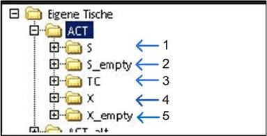
4.1.3 Creating a Setup (Assigning Tables)
► Copy an existing setup of your line.
► Replace the tables by using the prepared tables for ACT that you have already imported.(see
section 3.2.6).
Tables are available for any machine.
Key:
(1) S-tables with setup (4) X-tables with setup
(2) Empty S-tables (5) Empty X-tables
(3) TC = Tray Changer (WPC/MTC)