ACT - Accuracy Check Tool.pdf - 第208页
ACT with SSW 7xx / User Manual 07/2017 Edition 100 Figure 6-13: Conveyor configuration – V acuum tooling parameter Figure 6-14: Conveyor configuration – Maximum current at lifti ng table
ACT with SSW 7xx / User Manual 07/2017 Edition
99
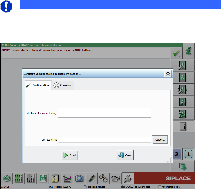
► Click the Edit button and import the data from the enclosed USB stick of the respective vacuum
tooling for each conveyor lane (2).
NOTICE
The serial number of the vacuum tooling is composed as follows:
Item number_4-digit sequential number
Lane 1 and Lane 2 have different material numbers!
Figure 6-12: Loading correction data
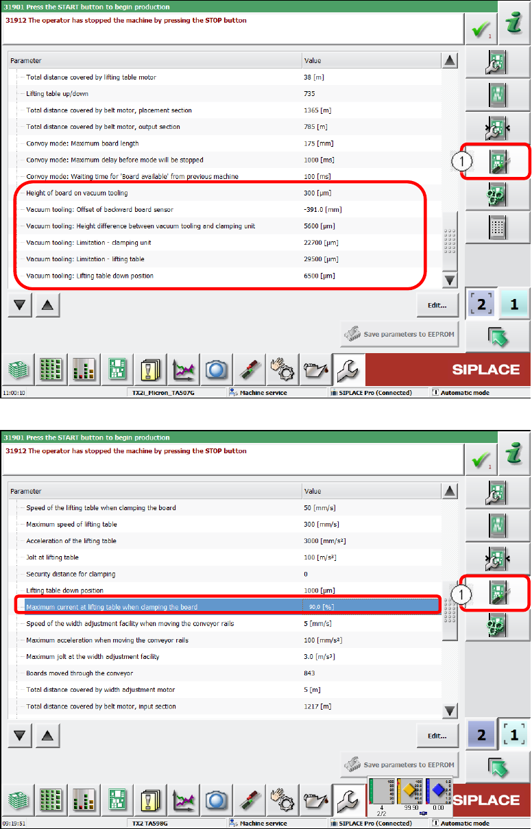
► Under Conveyor configuration switch over to the Conveyor lane set parameter view (1).
► Set the corresponding values as displayed in Figure 6-13 and Figure 6-14.
ACT with SSW 7xx / User Manual 07/2017 Edition
100
Figure 6-13: Conveyor configuration – Vacuum tooling parameter
Figure 6-14: Conveyor configuration – Maximum current at lifting table
ACT with SSW 7xx / User Manual 07/2017 Edition
101
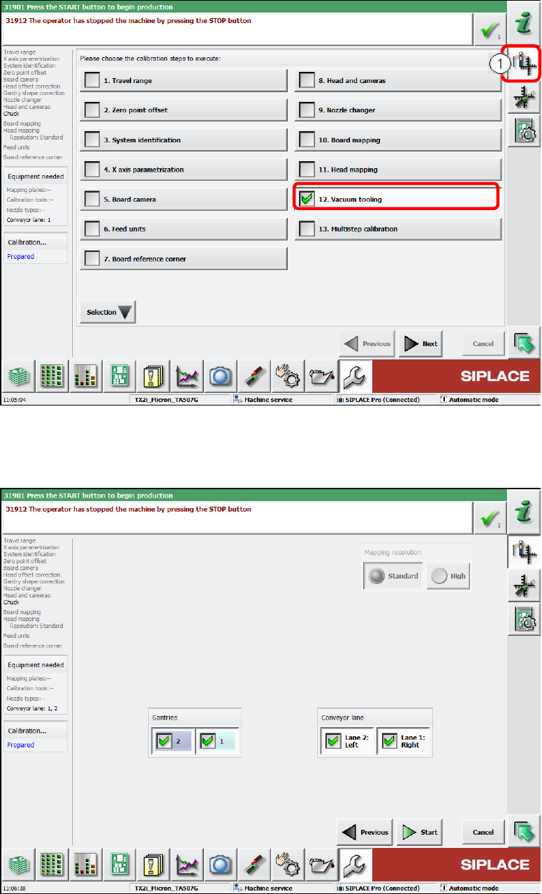
► Calibrate both vacuum toolings.
► Switch over to the Automatic calibration view (1).
► Select the Vacuum tooling calibration step.
Figure 6-15: Calibrating vacuum tooling, part 1
► Select both gantries and the conveyor lanes 1 and 2.
► Click the Start button.
Figure 6-16: Calibrating vacuum tooling, part 2