Autosite_Users_Manual.pdf - 第16页
Introduc tion 1-2 Aut oSi te User Manua l Package Contents Figure 1-1 shows the contents of the AutoSite system. Note : If you pu rchas ed a Pr oMaste r system , the con trol uni t will a lready be installed in t he hand…

AutoSite User Manual 1-1
Introduction
What Is AutoSite?
The AutoSite Automated Production Programmer is designed
specifically for use with device handlers in a production environment.
AutoSite employs “pin driver at the pin” technology, which allows the
pin drivers to be as close to the device as possible.
AutoSite supports virtually every programmable memory, logic, and
microcontroller device in DIP, PLCC, and most SOIC packages. Device
support is available through use of different programming modules, each
of which is designed for a specific package type and device pin count.
With programming modules, you can customize device support to suit
your specific programming needs and budget.
AutoSite is composed of two main pieces: the control unit and the pin
driver head. The control unit contains the disk drive, the serial ports, the
power supply, and the circuitry that generates control signals that are
sent to the pin driver head. The pin driver head receives the control
signals from the control unit and generates the voltages necessary to
program a device.
AutoSite comes in two configurations: support for up to 88 pins, with
8MB of RAM; and support for up to 44 pins, with 8MB of RAM. The 44-
pin configuration can easily be upgraded to the 88-pin configuration.
1
Introduction
1-2 AutoSite User Manual
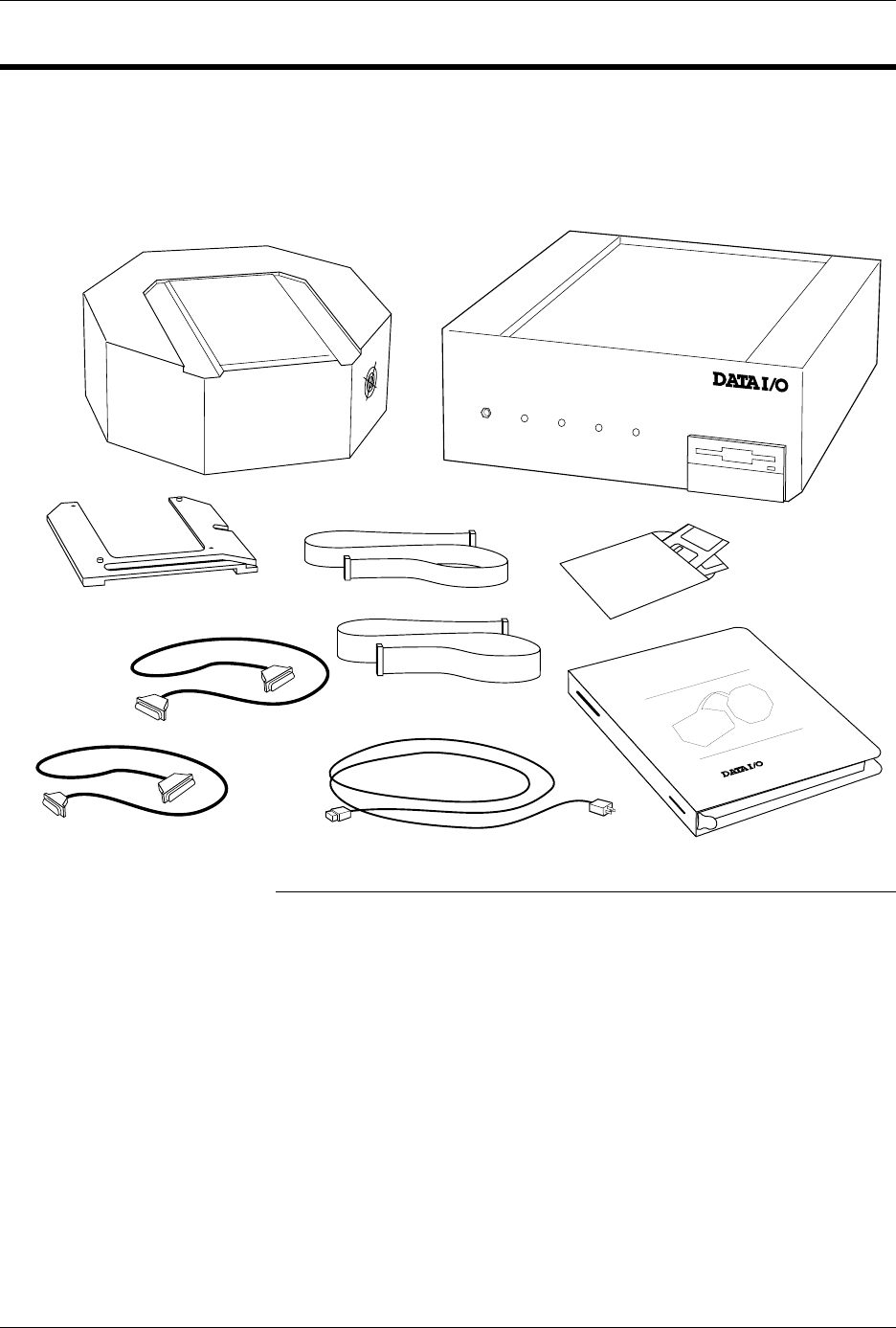
Package Contents
Figure 1-1 shows the contents of the AutoSite system.
Note: If you purchased a ProMaster system, the control unit will already be
installed in the handler.
If you purchased a non-ProMaster system, you should have received a
handler interface kit from your handler manufacturer. See the
documentation supplied with the interface kit for more information and for
a list of the kit’s contents.
Figure 1-1
AutoSite Package Contents
POWER
AUXILIARY
HANDLER
SELF TEST
AUTOSITE
DISKS
POWER CORD
USER
MANUAL
1353-6
PIN DRIVER HEAD
CONTROL UNIT
PROGRAMMING MODULE
CLAMP RING
50-PIN CABLE
68-PIN CABLE
AutoSite
25-PIN TO 25-PIN
RS-232 CABLE
9-PIN TO 25-PIN
RS-232 CABLE
Introduction
AutoSite User Manual 1-3
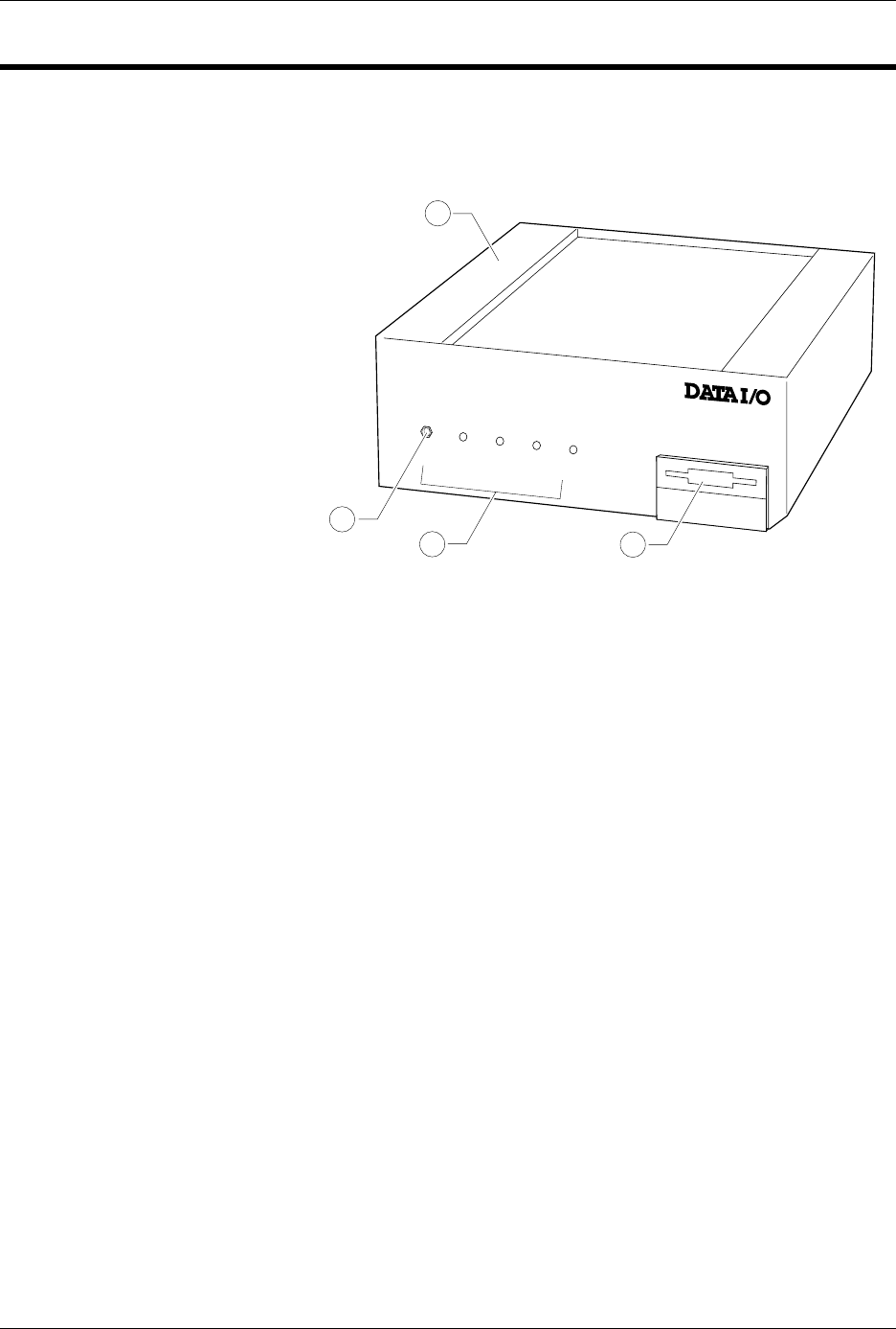
AutoSite External Features
The Control Unit
The front panel features of the control unit are shown in Figure 1-2.
1.
Control Unit
—Houses the circuitry that controls the pin driver head.
2.
Ground Connection
—Connect an antistatic wrist strap here.
3.
AutoSite Status Indicators
—These indicators provide information
about AutoSite’s operational status:
• Self-Test Indicator—This lamp is lit when AutoSite is performing a
self-test.
• Handler Indicator—This lamp is lit when AutoSite is
communicating with the equipment connected to AutoSite’s
Handler port.
• Auxiliary Indicator—This lamp is lit when AutoSite is
communicating with the equipment connected to AutoSite’s
Auxiliary port.
• Power Indicator—This lamp is lit when the power is on.
4.
Disk Drive
—Insert the Boot disk and Algorithm/System disk here.
Figure 1-2
Front Panel Features
POWER
AUXILIARY
HANDLER
SELF TEST
1300-2
1
2
3
4