Autosite_Users_Manual.pdf - 第18页
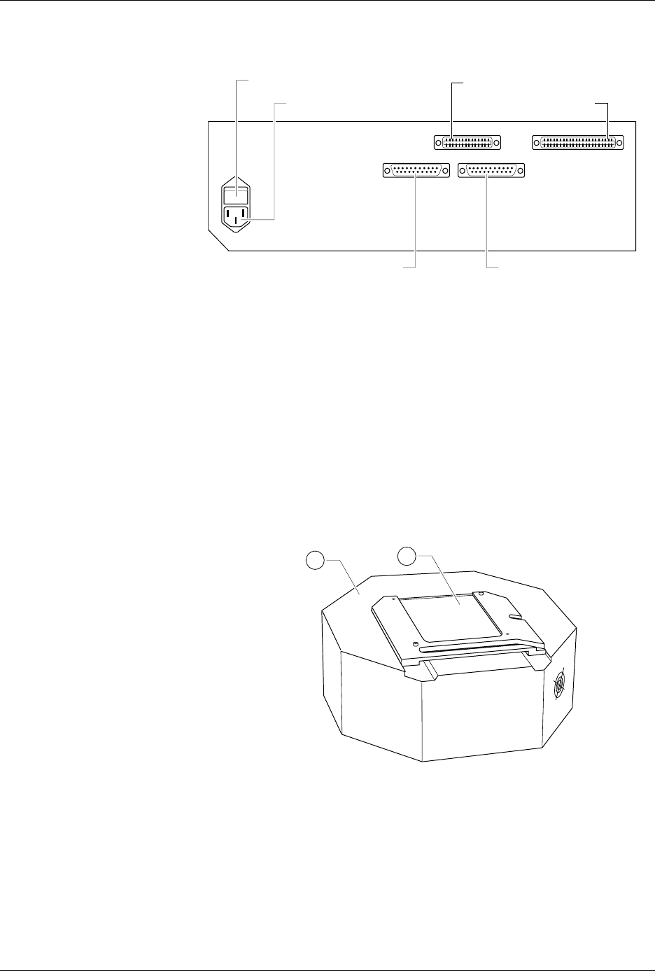
Introduc tion 1-4 Aut oSi te User Manua l The back panel featu res of the control unit are shown in F igure 1-3. • ac Receptacle—Connects AutoSite to ac power. • Power Switch—Applies ac pow er to AutoSite. • Handl er Por…
Introduction
AutoSite User Manual 1-3
AutoSite External Features
The Control Unit
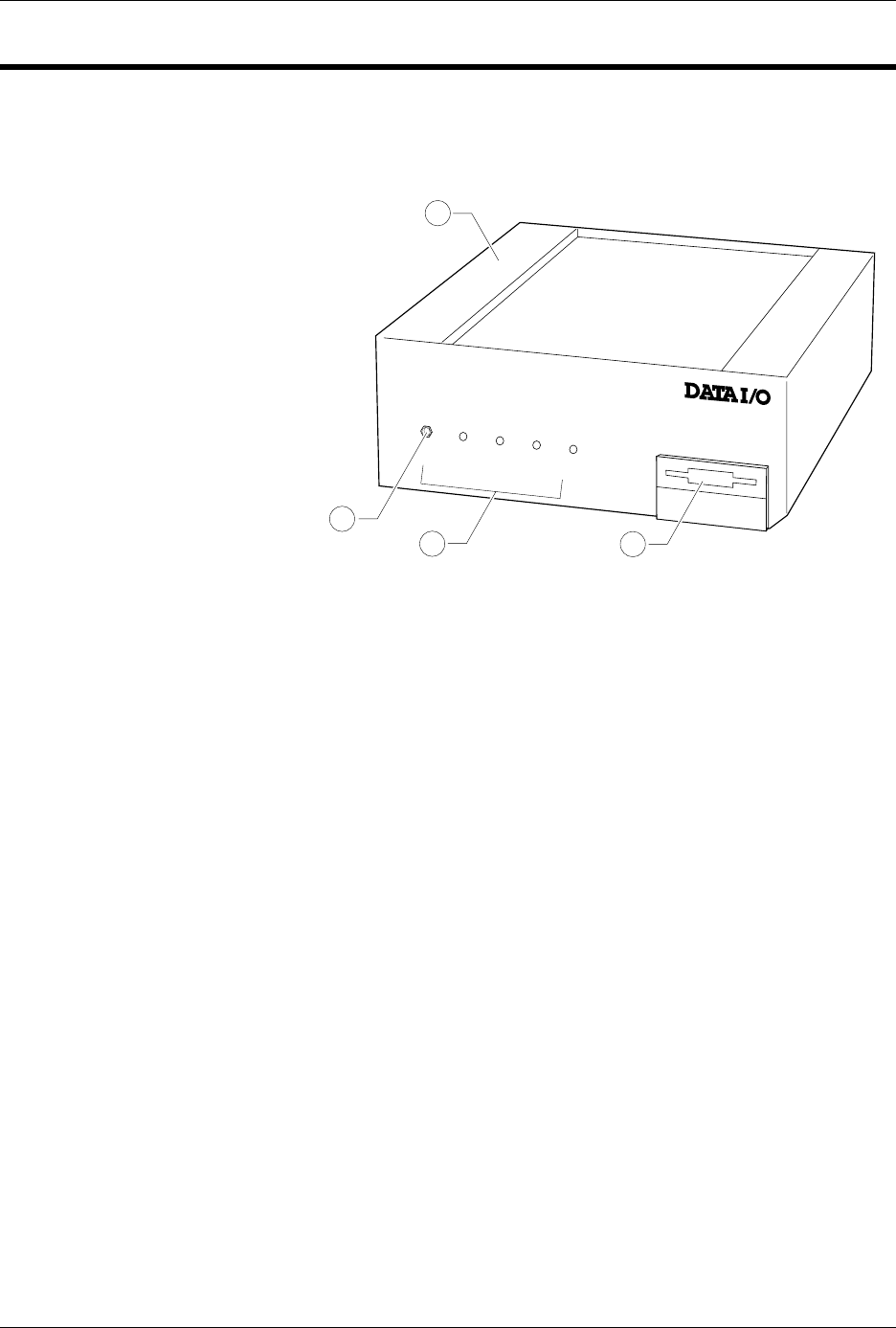
The front panel features of the control unit are shown in Figure 1-2.
1.
Control Unit
—Houses the circuitry that controls the pin driver head.
2.
Ground Connection
—Connect an antistatic wrist strap here.
3.
AutoSite Status Indicators
—These indicators provide information
about AutoSite’s operational status:
• Self-Test Indicator—This lamp is lit when AutoSite is performing a
self-test.
• Handler Indicator—This lamp is lit when AutoSite is
communicating with the equipment connected to AutoSite’s
Handler port.
• Auxiliary Indicator—This lamp is lit when AutoSite is
communicating with the equipment connected to AutoSite’s
Auxiliary port.
• Power Indicator—This lamp is lit when the power is on.
4.
Disk Drive
—Insert the Boot disk and Algorithm/System disk here.
Figure 1-2
Front Panel Features
POWER
AUXILIARY
HANDLER
SELF TEST
1300-2
1
2
3
4
Introduction
1-4 AutoSite User Manual
The back panel features of the control unit are shown in Figure 1-3.
• ac Receptacle—Connects AutoSite to ac power.
• Power Switch—Applies ac power to AutoSite.
• Handler Port—Connects AutoSite to a PC.
• Auxiliary Port—Used for system diagnostics and field service.
• 50-pin Cable Port—A 50-pin cable attaches here, connecting the
AutoSite control unit to the pin driver head.
• 68-pin Cable Port—A 68-pin cable attaches here, connecting the
AutoSite control unit to the pin driver head.
The Pin Driver Head
The features of the pin driver head are shown in Figure 1-4.
1.
Pin Driver Head
—Contains the universal pin drivers that supply
power and ground to either 44 or 88 pins, depending on your system
configuration.
2.
Programming Site
—Programming modules, the DIP Base, and the
PLCC Base fit here, connecting the pin drivers in the pin driver head to
the socketed device.
Figure 1-3
Back Panel Features
Figure 1-4
Pin Driver Head Features
1379-2
AC RECEPTACLE
POWER SWITCH
HANDLER PORT
AUXILIARY PORT
50-PIN CABLE PORT
68-PIN CABLE PORT
J2 J1
1389-1
1
2

Introduction
AutoSite User Manual 1-5
Specifications
Functional
RAM
8 MB standard (on units shipped after July
1997)
Disk Format, Floppy
Double-sided, Quad-density 3.5-inch disk
with 135 tracks per inch. 1.44MB formatted
Disk Format, MSM
(optional hard drive)
Minimum of 80MB
Controller
Motorola 68000 16-bit microprocessor
Terminal Support
Interfaces with ANSI 3.64 compatible
terminals, IBM PCs and compatibles
running a terminal emulator program, and
many popular ASCII terminals
Communication
Standard
RS-232C
Data transfer rate
110 to 19.2 K baud (up to 115.2K baud
using TaskLink)
Power Requirements
Operating Voltages
90 to 264 Vac
Frequency Range
50–60 Hz
Power Consumption
150 VA maximum
Input Current
1.5A maximum
Physical and
Environmental
Dimensions
Control unit:
Pin driver head:
Weight
7.7 kg (17 lbs.)
Temperature
Operating: +5° to 40°C (+40° to 105°F)
Storage: +5° to 50°C (+40° to 122°F)
Transportation:
-40° to +55°C (-40° to +130°F)
Relative Humidity
Operating: to 80% noncondensing
Storage: to 90% noncondensing
Altitude
Operating: to 15,000 meters
17.15h x 33.65w x 28.5d cm
6.75h x 13.25w x 11.25d in.
8.9h x 27.3w cm
3.5h x 10.75w in.