Autosite_Users_Manual.pdf - 第27页
Setup an d Installa tion AutoSite User Manual 2-5 5. Move the four rubber pads from the bottom of the control unit to the edge of the control unit opposite the bevelled edge. 6. Locate the fan opening on the back of the …
Setup and Installation
2-4 AutoSite User Manual
Attaching the
Control Unit
Connect the AutoSite control unit to a ProMaster 2000 as follows:
1. Unplug the power cord from the AutoSite control unit.
2.
(For control units without connector brackets at ports J1 and J2)
Make sure
the 50-pin cable and the 68-pin cable are disconnected from the
control unit and the pin driver head. The cables and the ports to
which they connect are shown in Figures 1-1 and 1-3.
(For control units with connector brackets at ports J1 and J2)
Make sure
the 50-pin cable and the 68-pin cable are disconnected from the pin
driver head.
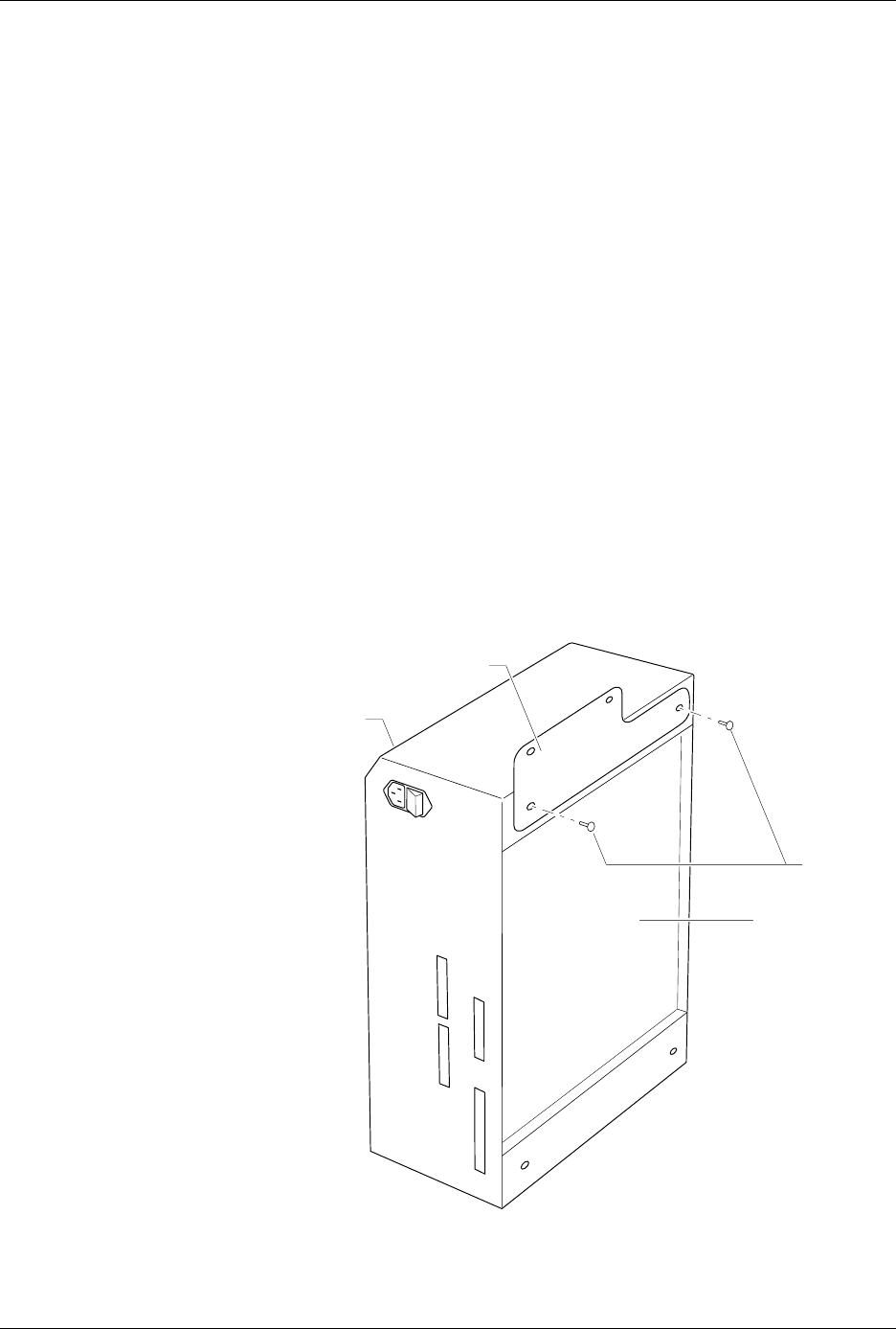
3. Locate the two flathead screws shown in Figure 2-2 and remove them
from the control unit. Set these screws aside; you will need them
later.
4. As shown in Figure 2-2, position the control unit mounting plate
against the control unit so the countersunk holes on the control unit
mounting plate are facing away from the control unit. Also, make
sure that the narrow end of the control unit mounting plate is
pointing toward the disk drive on the control unit.
Secure the control unit mounting plate to the control unit with the
two flathead screws you removed in step 3. Tighten the screws with a
#2 Phillips screwdriver. Do not overtighten the screws.
Figure 2-2
Attaching the Control Unit
Mounting Plate to the Control Unit
1344-1
SCREWS
BEVELED
EDGE
CONTROL UNIT
MOUNTING PLATE
CONTROL UNIT
Setup and Installation
AutoSite User Manual 2-5
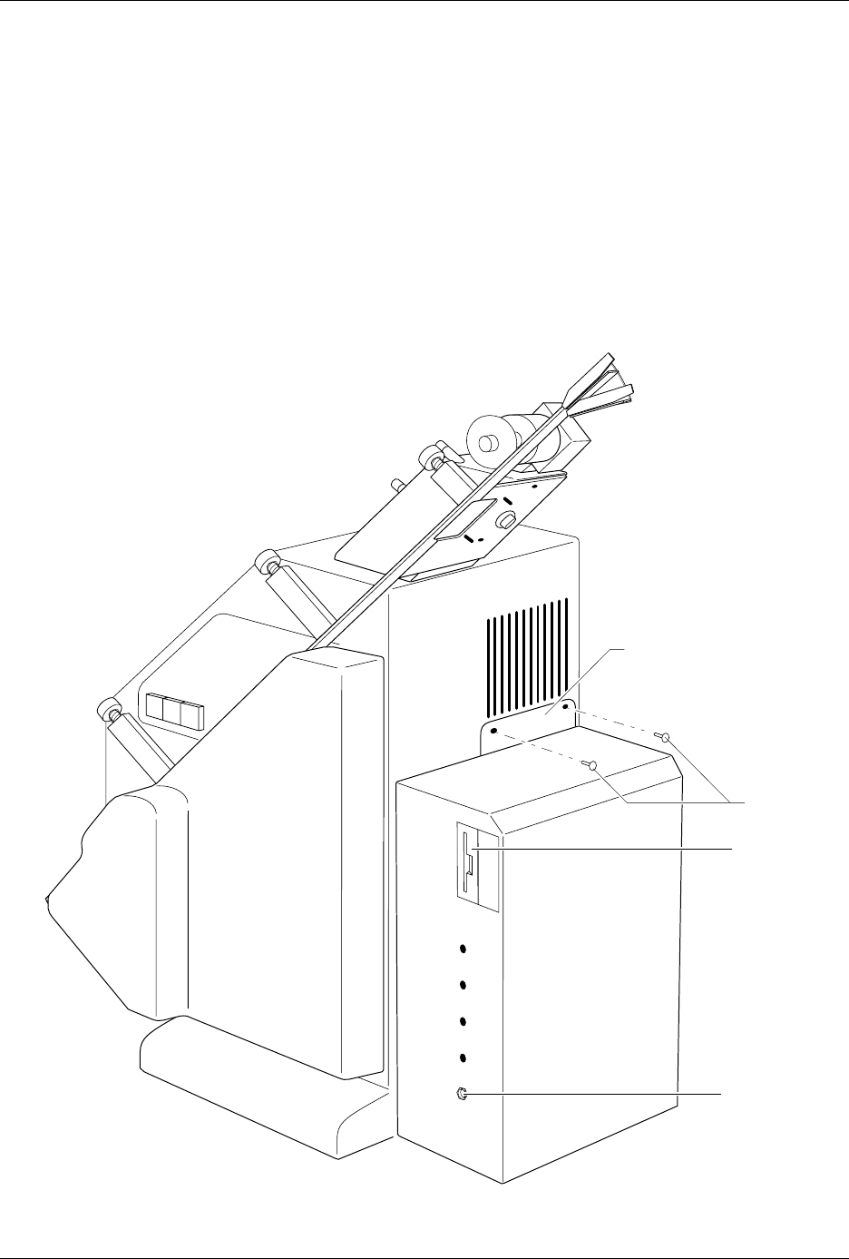
5. Move the four rubber pads from the bottom of the control unit to the
edge of the control unit opposite the bevelled edge.
6. Locate the fan opening on the back of the 2000. Using a 5/32-inch hex
driver, remove the two screws on the bottom edge of the fan opening.
Discard these screws; you will not need them later. Position the
control unit against the back of the handler as shown in Figure 2-3.
The control unit should be sitting on its four rubber pads.
7. Attach the control unit to the handler with the two buttonhead
screws provided. Tighten the screws with a 5/32-inch hex driver. Do
not overtighten the screws.
Figure 2-3
Attaching the Control Unit to the ProMaster 2000
1345-1
CONTROL UNIT
MOUNTING PLATE
DISK DRIVE
GROUND
WRIST STRAP
CONNECTOR
SCREWS
Setup and Installation
2-6 AutoSite User Manual
Converting a
Contactor Set
This section describes how to convert a contactor set for use with
AutoSite.
Note: If you purchased AutoSite and the ProMaster 2000 at the same time, each
contactor set sent with the 2000 is ready for use with AutoSite. Go to step
6 to continue with the setup and installation.
If you purchased AutoSite and the 2000 separately (i.e., you are
connecting AutoSite to an existing 2000), you must convert each
contactor set you have before you can use it with AutoSite.
Follow the steps below to convert a contactor set for use with AutoSite:
1. Unplug the power cord from the AutoSite control unit.
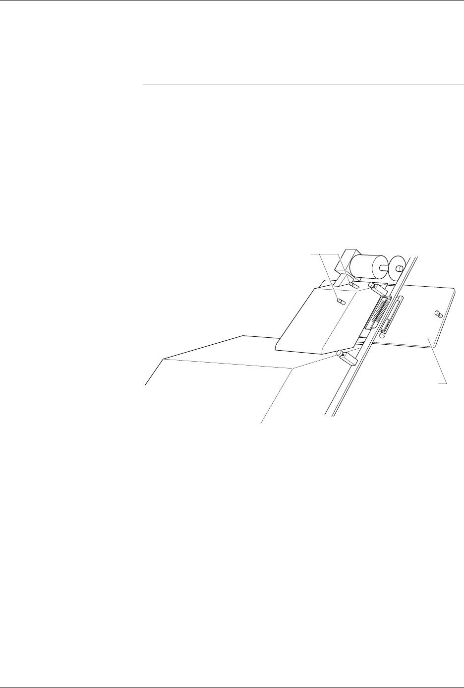
2. Remove the contactor set from the 2000 by loosening the two
thumbscrews shown in Figure 2-4. With the thumbscrews loosened,
lower the contactor set from the 2000.
3. Using a 5/32-inch hex driver, remove the four hex head screws
shown in Figure 2-5. Discard these screws; you will not need them
later.
Figure 2-4
Removing the Contactor Set from
the ProMaster 2000
1346-1
CONTACTOR SET
THUMBSCREWS