Autosite_Users_Manual.pdf - 第35页
Setup an d Installa tion AutoSite User Manual 2-13 Before You Begin Dependin g on when you purcha sed you r ProMas ter 3000 ( or ProMast er 7000) and AutoSite, you mi ght not have to ins tall AutoSite into you r handle r…

Setup and Installation
2-12 AutoSite User Manual
(For control units and pin driver heads with connector brackets at ports J1
and J2.)
Remove the two screws that hold the connector shell together
at the unconnected end of the 50-pin cable. Plug the 50-pin cable into
the appropriate port on the pin driver head and fasten it to the
connector bracket by aligning the holes in the bracket with the holes
on the connector shell and reinserting the screws through the holes.
Tighten the screws.
Repeat the procedure for the 68-pin cable.
Checking the
Installation
When properly connected to the handler, the mounting brackets attached
to the pin driver head will be flush against the pin driver head mounting
plate.
If the mounting brackets are not flush against the pin driver head
mounting plate, detach the pin driver head from the pin driver head
mounting plate and go back to step 10.
You are finished connecting AutoSite to your 2000. Go to the section titled
“Power Up AutoSite,” on page 2-27, to continue with the installation.
Connect AutoSite to a ProMaster 3000 or ProMaster 7000
Handler
Note: The procedure for connecting AutoSite to a ProMaster 3000 is almost the
same as the procedure for connecting AutoSite to a ProMaster 7000.
Differences between the two procedures will be pointed out at the
appropriate times in this section.
This section describes how to install AutoSite in a ProMaster 3000
handler. The installation is divided into four main steps:
• Removing the programmer shelf from the 3000
• Rerouting the optics on the 3000
• Installing the AutoSite control unit in the 3000
• Attaching the AutoSite pin driver head to the 3000
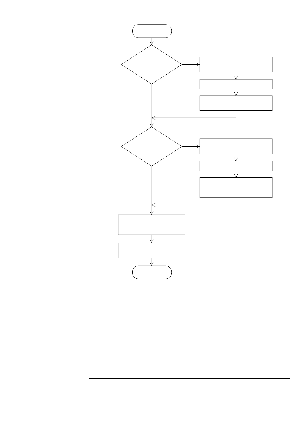
Figure 2-12 is a flowchart that illustrates the general flow of the
installation procedures contained in this section.
Safety Information
This information is provided as a supplement to the Safety Summary at
the beginning of this manual.
The circuitry housed inside the pin driver head and the control unit, and
the devices AutoSite programs are static sensitive and can be damaged by
electrostatic discharge (ESD). To help minimize the effects of ESD, we
suggest you wear an antistatic wrist strap while you follow the
procedures described in this section.
For best performance, the antistatic wrist strap should be connected to a
properly grounded antistatic workstation and the wrist strap should
contain a 1M
Ω
(minimum) to 10M
Ω
(maximum) isolating resistor.
Setup and Installation
AutoSite User Manual 2-13
Before You Begin
Depending on when you purchased your ProMaster 3000 (or ProMaster
7000) and AutoSite, you might not have to install AutoSite into your
handler. All new ProMaster 3000 and ProMaster 7000 handler systems
come with the AutoSite programmer installed. If this is the case, skip this
section and continue to the section titled “Connect the Pin Driver Head,”
on page 2-21.
Some older ProMaster 3000 and ProMaster 7000 handlers were sold
without the AutoSite, in which case you have to install the AutoSite
control unit into your handler. In this case, continue with the section
titled “What You Need.”
Note: All directional references—front, back, left, right, up, and down—are as if
you are looking at the front of the handler.
Figure 2-12
Flowchart of the Installation
Process for the ProMaster 3000 or
the ProMaster 7000
1414-1
START
CONTROL
UNIT ATTACHED
TO HANDLER ?
CONVERT
TEST SITE TO
PROGRAMMING
MODULE?
REMOVE
PROGRAMMER SHELF
REROUTE OPTICS
ATTACH CONTROL UNIT
TO HANDLER
DISASSEMBLE
TEST SITE
REMOVE IDENTIFICATION FIN
ATTACH PROGRAMMING
MODULE BLOCK
TO TEST SITE
N
Y
N
Y
ATTACH PROGRAMMING
MODULE TO PIN
DRIVER HEAD
ATTACH PIN DRIVER
HEAD TO HANDLER
FINISH

Setup and Installation
2-14 AutoSite User Manual
What You Need
In addition to the contents of the Installation Kit, you will need the
following tools and equipment to help you install AutoSite in your
handler.
•Programming module
• Grounded wrist strap
• Antistatic workstation
• 5/32-inch hex driver
• 5/64-inch hex driver
• Flat blade screwdriver
• #2 Phillips screwdriver
• Small wire cutters
Remove the
Programmer Shelf
This section describes how to remove the programmer shelf from the
3000. This section does not apply to a 7000. If you are installing AutoSite
into a 7000, skip to the section titled “Reroute the Optics,” on page 2-17.
CAUTION: In this section, you will be working with the programmer
shelf on the 3000. The shelf is supported by an air shock and
can spring up when you turn the knob or when you detach
the shock from the programmer shelf.
Use caution when adjusting the programmer shelf or
working with the air shock.
1. Power down the handler and the programmer.
2. Loosen the knob on the programmer shelf and push the shelf to its
bottom-most position. Tighten the knob to lock the shelf in place.
3. Remove any programmer, such as an AutoSite, from the programmer
shelf in the handler.
4. Remove any tests sites, programming fixtures, or performance
boards from the programming station on the handler.
5. Remove the metal underplate from the 3000 by lifting the underplate
up and sliding it toward you. Discard the metal underplate; you will
not need it later.
6. Loosen the knob on the programmer shelf and raise the shelf to its
topmost position. Tighten the knob to lock the shelf in place.