Autosite_Users_Manual.pdf - 第39页
Setup an d Installa tion AutoSite User Manual 2-17 12. Usi ng a 5/32- inch hex d river, remove th e eight hex he ad screws on the left side of the programmer shelf. Set these screws aside; you will need them later. Note:…
Setup and Installation
2-16 AutoSite User Manual
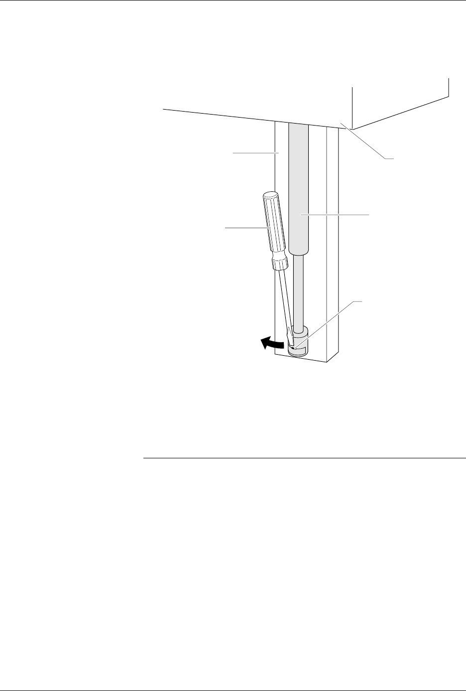
7. Insert a flat blade screwdriver into the notch shown in Figure 2-14.
Disconnect the bottom of the air shock by twisting the blade of the
screwdriver and pulling the bottom of the air shock toward you.
8. Loosen the knob on the programmer shelf and push the programmer
shelf to its bottom-most position.
9. Using a 5/64-inch hex driver, remove the three hex head screws on
the right side of the back of the programmer shelf. Discard these
screws; you will not need them later.
Note: When you remove the last of the three screws, the shelf guide and air shock
assembly will slide off the track.
10. After you have removed all three screws, remove the shelf guide
from the track. Set the shelf guide and the air shock aside; you will
need them later.
11. Remove the knob and shaft from the programmer shelf by turning
the knob counterclockwise. Discard the knob and shaft; you will not
need them later.
Figure 2-14
Disconnecting the Air Shock
1408-2
TRACK
AIR SHOCK
ASSEMBLY
NOTCH
PROGRAMMER
SHELF
SCREW DRIVER
Setup and Installation
AutoSite User Manual 2-17
12. Using a 5/32-inch hex driver, remove the eight hex head screws on
the left side of the programmer shelf. Set these screws aside; you will
need them later.
Note: Support the shelf before you remove the last few screws. The shelf will fall
from the 3000 when you remove the last screw.
13. After you have removed all eight screws, remove the programmer
shelf and discard it. You will no longer need the programmer shelf.
Reroute the Optics
Follow the steps below to reroute the optics on the 3000 (or 7000):
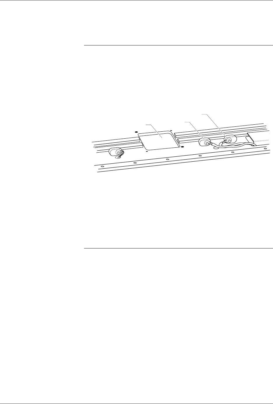
1. Locate the two optics shown in Figure 2-15.
2. Working with one optic at a time, follow the steps below:
a. Trace the optic wire back to its connector.
b. Disconnect the connector.
c. Feed the optic wire back through the hole so the optic wire is
above the programming track.
d. Feed the optic wire down through the new opening.
e. Reconnect the optic wire to the connector.
Note: You may have to cut a cable tie to free up enough of the optic wire to allow
you to reroute the optic through the new opening.
3. Repeat the procedure described in step 2 with the other optic shown
in Figure 2-15.
4. Using a cable tie, secure the rerouted optic wires to an adjacent wire
bundle.
Figure 2-15
Rerouting Two Optics
OPTIC 1
1409-1
OPTIC 2
PROGRAMMING STATION
Setup and Installation
2-18 AutoSite User Manual
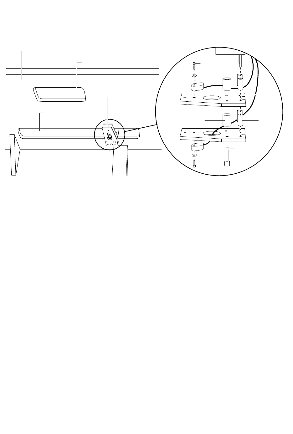
5. Locate the test site reader optic, which is shown in Figure 2-16.
6. Using a 5/64-inch hex driver, remove the lower optic from the lower
plate. Discard the hex head screw and the washer; you will not need
them later.
7. Using a hex driver, loosen, but do not remove, the large hex screw
shown in Figure 2-16.
8. Hold the lower plate in place while you remove the hex screw from
the handler. When you remove the screw, remove the plate and the
three lower standoffs from the handler. Discard the lower plate and
the lower standoffs; you will not need them later.
9. Remove the upper plate and the three upper standoffs from the
handler. Discard the upper standoffs; you will not need them later.
10. Using a 5/64-inch hex driver, remove the upper optic from the upper
plate. Discard the upper plate, the hex head screw, and the washer;
you will not need them later.
11. Using a cable tie, secure the two optic read heads together.
12. Make certain that you secure the optics so they do not interfere with
the full travel of beam 1 to both ends of its run. Push beam 1 all the
way to the right and left to check the optics do not interfere with the
full travel of the beam.
Figure 2-16
The Location of the Test Site Reader Optic
1410-1
SMALL
SPACER
(1 of 4)
LARGE SPACER
(1 of 2)
LARGE HEX
HEAD
SCREW
PLATE
(1 of 2)
PROGRAMMING STATION
UNDER SIDE OF HANDLER
SMALL HEX
HEAD SCREW
(1 of 2)
OPTIC
( 1 of 2)
TRACK
TEST SITE
READER OPTIC
OPENING FOR
BEAM 1