Autosite_Users_Manual.pdf - 第43页
Setup an d Installa tion AutoSite User Manual 2-21 Connect the Pin Driver Head Connect t he AutoSite pi n driver hea d to a ProM aster 30 00 handler as follows: 1. Loosen th e knob and mo ve the control unit dow n, givin…

Setup and Installation
2-20 AutoSite User Manual
5. Using a 5/64-inch hex driver and the two hex head screws provided,
fasten the conversion plate onto the back of the AutoSite control unit.
6. Slide the control unit and the shelf guide onto the track. Make sure
the bearings on the shelf guide are properly positioned on the track.
7. Using a #2 Phillips screwdriver and the four flathead screws
provided, fasten the left side of the control unit to the mounting plate.
8. Slide the control unit up and down the track, checking for proper
alignment and installation.
9. Loosen the knob on the control unit and raise the control unit to its
topmost position.
10. Reconnect the air shock to the 3000.
11. Slide the control unit up and down the track, checking for proper
installation of the air shock.
12. Loosen the knob on the control unit and lower the control unit to its
bottom-most position.
13. Install the new metal underplate on the 3000.
Convert a Test Site to
a Programming
Module
If you are installing AutoSite into an existing handler (i.e., you did not
buy the handler and AutoSite at the same time), you will need to convert
your existing test sites into AutoSite compatible programming modules.
If you purchased AutoSite and the 3000 (or 7000) at the same time, each
programming module sent with the 3000 is ready for use with AutoSite.
Go to the section titled “Connect the Pin Driver Head,” on page 2-21, to
continue with the setup and installation.
For more information, see the documentation supplied with the
Conversion Kit.
Setup and Installation
AutoSite User Manual 2-21
Connect the Pin
Driver Head
Connect the AutoSite pin driver head to a ProMaster 3000 handler as
follows:
1. Loosen the knob and move the control unit down, giving you more
room to work.
2. Remove any test site from the programming station on the 3000.
3. Verify that the 50-pin cable and the 68-pin cable are connected and
properly fastened to the AutoSite control unit. Do not connect the
other end of the 50-pin and 68-pin cables yet. The 50-pin cable and 68-
pin cable and the ports they connect to are shown in Figures 1-1 and
1-3.
4.
(For control units without connector brackets at ports J1 and J2.)
The
50-pin and 68-pin cables click when properly connected.
5. Connect a 25-pin RS-232C serial cable to the Handler port on the
AutoSite control unit. Refer to Figure 1-3 for the location of the
Handler port.
6. Connect the other end of the serial cable to a serial port on the PC.
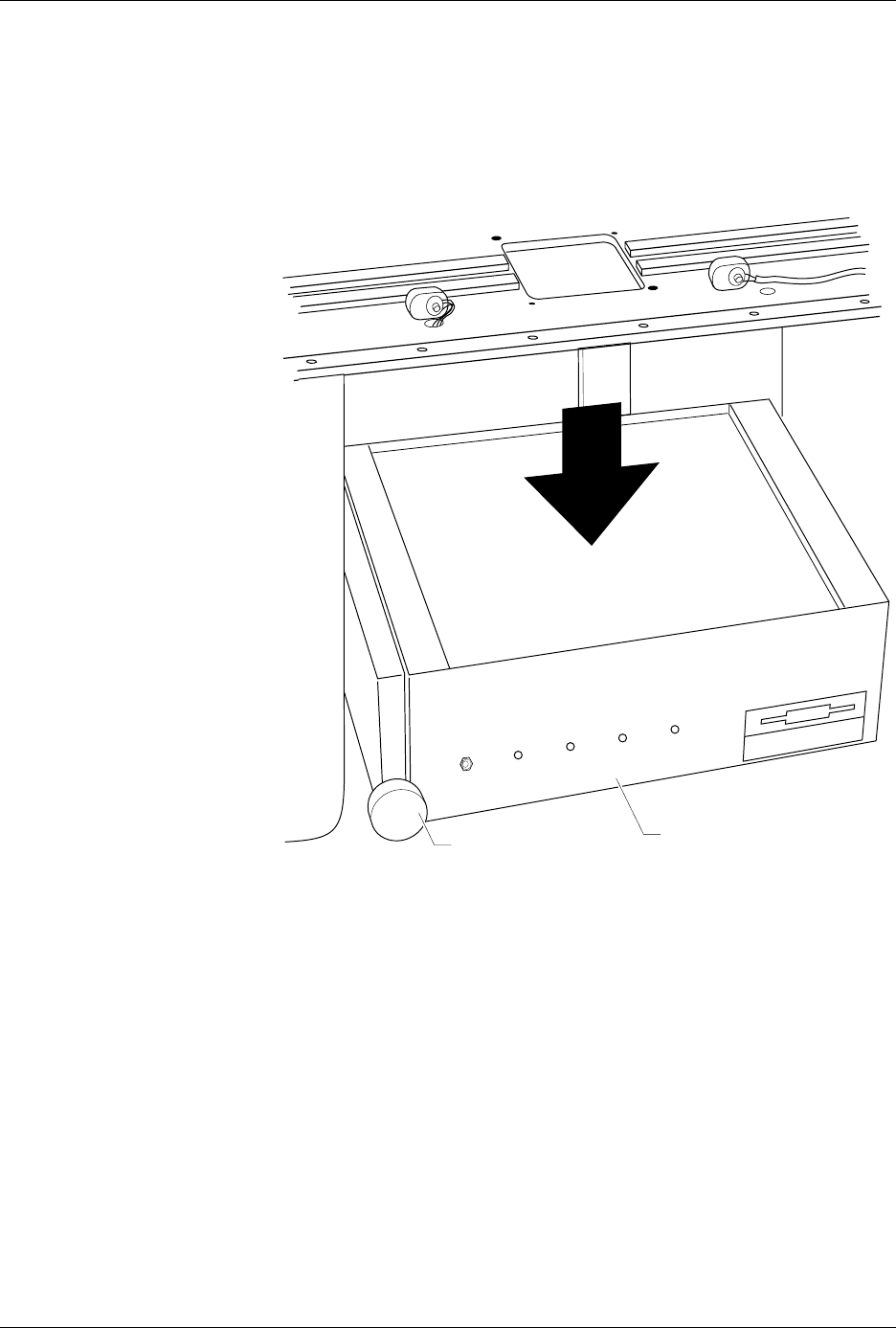
Figure 2-18
Lowering the Control Unit
1416-1
CONTROL UNIT
KNOB
POWER
AUXILIARY
HANDLER
SELF TEST
Setup and Installation
2-22 AutoSite User Manual
Note: See the section in this chapter titled “More About Cables” if you are using
a serial port with nonstandard pinouts or if you want to build your own
serial cable.
7. If the clamp ring is installed on the pin driver head, slide the clamp
ring off and set it aside; you will need it later. The clamp ring is
shown in Figure 2-10.
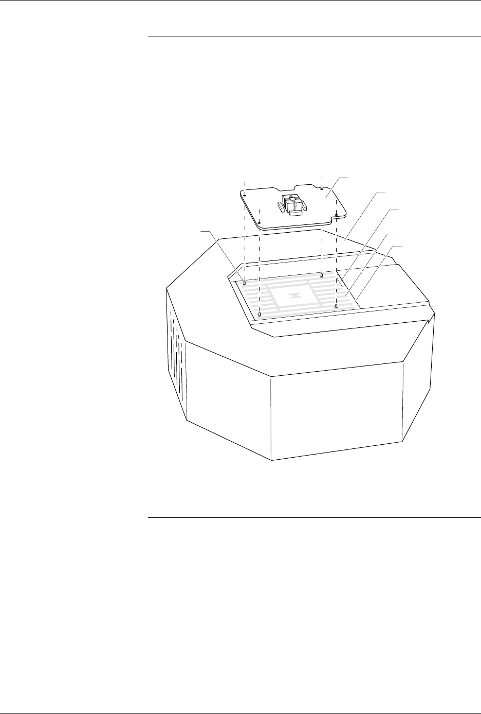
8. As shown in Figure 2-19, set a programming module onto the pin
driver head, making sure the guide pins on the pin driver head line
up with the guide holes in the programming module.
9. As shown in Figure 2-20, slide the clamp ring onto the pin driver
head, securing the new programming module in place.
CAUTION: You may have to push down on the programming module
while sliding the clamp ring onto the pin driver head.
Do not use the device socket on the programming module as
a leverage point. You can damage the device socket by
applying any sort of force to it.
You will feel and hear a “click” from the clamp ring when the
programming module is properly secured to the pin driver head.
Figure 2-19
Aligning a Programming Module
on the Pin Driver Head
1360-3
PROGRAMMING MODULE
GUIDE PIN
(1 of 4)
PIN DRIVER HEAD
SPA BLOCK
SQUIRT PINS
PART NUMBER
LABEL