Autosite_Users_Manual.pdf - 第46页
Setup and Ins tallation 2-24 Auto Site Us er Man ual 14. Low er the ho od on the handl er. Checking the Installation When p roper ly con nected to the handle r, th e clamp ring w ill be flush agai nst t he ha ndler. If t…
Setup and Installation
AutoSite User Manual 2-23
10.
(For pin driver heads without connector brackets at ports J1 and J2.)
Connect the other end of the 50-pin and 68-pin cables to the pin
driver head. The 50-pin and 68-pin cables click when properly
connected to the pin driver head.
(For pin driver heads with connector brackets at ports J1 and J2.)
Remove the two screws that hold the connector shell together at the
unconnected end of the 50-pin cable. Plug the 50-pin cable into the
appropriate port on the pin driver head and fasten it to the connector
bracket by aligning the holes in the bracket with the holes on the
connector shell and reinserting the screw through the holes. Tighten
the screws.
Repeat the procedure for the 68-pin cable.
11. Lift up the hood on the handler.
Note: Read the next two steps before proceeding with either step.
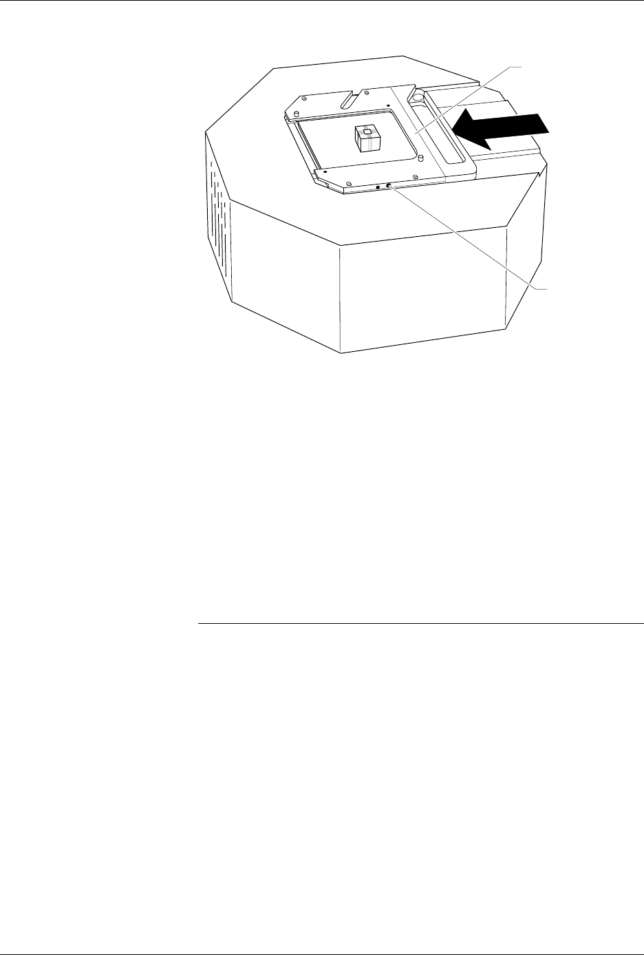
12. Position the pin driver head below the programming station with the
clamp ring to the right. Line up the guide pins on the programming
module with the guide pin holes in the handler.
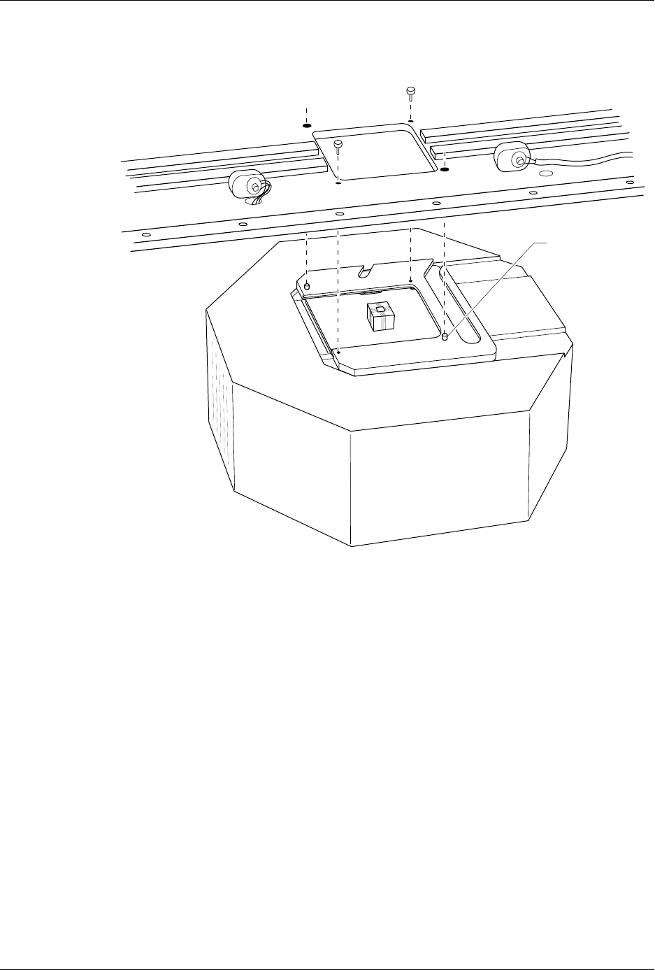
13. Using the two pin driver head thumbscrews provided, secure the pin
driver head to the handler. See Figure 2-21 for the location of the
holes for the thumbscrews.
Figure 2-20
Securing a Programming Module
to the Pin Driver Head
1361-2
PROGRAMMING
MODULE CLAMP RING
ADJUSTMENT
SCREW
Setup and Installation
2-24 AutoSite User Manual
14. Lower the hood on the handler.
Checking the
Installation
When properly connected to the handler, the clamp ring will be flush
against the handler.
If the clamp ring is not flush against the handler, remove the pin driver
head from the handler and go back to step 8.
You are finished connecting AutoSite to your ProMaster 3000 (or
ProMaster 7000). Go to the section titled “Power Up AutoSite” to
continue with the installation.
Figure 2-21
Securing the Pin Driver Head to the Handler
1362-1
GUIDE PIN
(1 of 2)

Setup and Installation
AutoSite User Manual 2-25
Connect AutoSite to a Non-ProMaster Handler
This section describes how to connect AutoSite to a handler. The
installation is divided into two main steps:
• Attach the AutoSite control unit to the handler
• Attach the AutoSite pin driver head to the handler
Before you begin, you must set up your handler and install your handler
control software. Refer to the documentation that came with your handler
and handler control software for information.
What You Need
In addition to the contents of the Installation Kit, which is supplied by the
handler manufacturer, you will need the following to connect AutoSite to
a handler:
• Grounded wrist strap
Note: Contact the handler manufacturer if you did not receive hardware for
connecting AutoSite to your handler.
Safety Information
This information is provided as a supplement to the Safety Summary at
the beginning of this manual.
The circuitry housed inside the pin driver head and the control unit, and
the devices AutoSite programs are static sensitive and can be damaged by
electrostatic discharge (ESD). To help minimize the effects of ESD, we
suggest you wear an antistatic wrist strap while you follow the
procedures described in this section.
For best performance, the antistatic wrist strap should be connected to a
properly grounded antistatic workstation and the wrist strap should
contain a 1M
Ω
(minimum) to 10M
Ω
(maximum) isolating resistor. We
suggest you connect your antistatic wrist strap to the grounding terminal
on the front of the AutoSite control unit. The grounding terminal is
shown in Figure 1-2.
Attaching the
Control Unit
Connect the AutoSite control unit to a handler as follows:
1. Verify that the 50-pin cable and the 68-pin cable are connected and
properly fastened to the AutoSite control unit. Do not connect the
other end of the 50-pin and 68-pin cables yet. The 50-pin cable and 68-
pin cable and the ports to which they connect are shown in Figure 1-1
and Figure 1-3.
(For control units without connector brackets at ports J1 and J2.)
The
50-pin and 68-pin cables click when properly connected.
2. If you will be controlling AutoSite from a PC, connect a 25-pin
RS-232C serial cable to the Handler port on the AutoSite control unit.
Refer to Figure 1-3 for the location of the Handler port.
Connect the other end of the serial cable to a serial port on the PC.