Autosite_Users_Manual.pdf - 第57页
Setup an d Installa tion AutoSite User Manual 2-35 * If these lines are not connected, AutoSite con siders them high and functions norm ally. Pin Functions Whe n In DCE Mode The following table explains the function of t…

Setup and Installation
2-34 AutoSite User Manual
6. Power up AutoSite.
7. Verify that AutoSite and the controlling software are communicating.
If you are using TaskLink, press
C
TRL
+
F1
to check communication
between TaskLink and AutoSite. If TaskLink displays
Contact With
Programmer Established
, then TaskLink and AutoSite are
communicating.
You are now ready to begin a new session on AutoSite.
More About Cables
This section describes the pin assignments AutoSite uses on its serial
ports. Use the information on this page and the following two pages to
build serial cables to connect to AutoSite.
SmartPort
AutoSite is compatible with both Data Terminal Equipment (DTE) and
Data Communications Equipment (DCE). AutoSite’s SmartPort feature
automatically toggles between DTE and DCE until a connection is
established.
Making Your Own
Cable
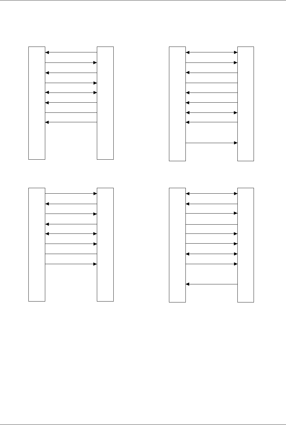
AutoSite receives commands and sends responses through an RS-232C
port using a 25-pin D connector in two possible configurations: either
DTE or DCE. The connections are shown in Figure 2-24.
Pin Functions When In
DTE Mode
The following table explains the function of the connector pins on the
Auxiliary and Handler ports when they are configured as DTE ports.
Pin Function Description
1 Ground Provides a safety ground connection
2 Transmit Data Carried the transmitted data
3 Receive Data Carries the received data
4 Request to Send This line is held high by AutoSite
5* Clear to Send A high on this line enables AutoSite to
transmit data. (Used for hardware
handshaking.) A low inhibits data
transmission from AutoSite.
6* Data Set Ready This line is held high when the remote source
is ready to send or receive data. A low
inhibits data transmission from AutoSite.
7 Signal Ground Provides a reference ground for all signals on
the cable.
8* Data Carrier
Detect
This line is held high when the modem
detects a carrier. A low on this line inhibits
AutoSite from transmitting data.

Setup and Installation
AutoSite User Manual 2-35
* If these lines are not connected, AutoSite considers them high and functions normally.
Pin Functions When In
DCE Mode
The following table explains the function of the connector pins on the
Auxiliary and Handler ports when they are configured as DCE ports.
* If this line is not connected, AutoSite considers it high and functions normally.
9-19 No Connection
20 Data Terminal
Ready
This line is pulled high by AutoSite to
indicate it is ready to receive data. This line is
pulled low to signal the PC to stop sending
data. (Used for hardware handshaking.)
21-25 No Connection
Pin Function Description
1 Ground Provides a safety ground connection
2 Receive Data Carries the received data from the DTE
device to AutoSite.
3 Transmit Data Carries the transmitted data from AutoSite to
the DTE device.
4 Request to Send This line is held high by AutoSite.
5 Clear to Send A high on this line from AutoSite means that
it is ready to receive data. (Used for
hardware handshaking.)
6 Data Set Ready This line is held high when AutoSite is ready
to transfer data.
7 Signal Ground Provides a reference ground for all signals on
the cable.
8 Data Carrier This line is held high by AutoSite.
9-19 No Connection
20* Data Terminal A high on this line enables AutoSite to
transmit data. (Used for hardware
handshaking.) A low inhibits data
transmission from AutoSite.
21-25 No Connection
Setup and Installation
2-36 AutoSite User Manual
Figure 2-24
Pin Designations for RS-232C Serial Port Connection
1
2
3
4
5
6
7
8
9-19
20
21-25
1
2
3
4
5
6
7
8
20
PROTECTIVE GND
DATA
DATA
RTS (HELD HIGH)
CTS
DSR
SIGNAL GND
DCD
DTR
NC
GND
RECEIVE
TRANSMIT
RTS
CTS
DSR
GND
DCD
DTR
TRANSMIT
RECEIVE
25 PIN
AUTOSITE (DTE)
25 PIN
MODEM (DCE)
1
2
3
4
5
6
7
8
9-19
20
21-25
1
2
3
4
5
6
7
8
20
PROTECTIVE GND
DATA
DATA
RTS (HELD HIGH)
CTS
DSR
SIGNAL GND
DCD (HELD HIGH)
DTR
NC
NC
GND
TRANSMIT
RECEIVE
RTS
CTS
DSR
GND
DCD
DTR
RECEIVE
TRANSMIT
25 PIN
AUTOSITE (DCE)
25 PIN
TERMINAL (DTE)
1373-1
The minimum hookup includes Pins 2, 3, and 7.
Pins 1 and 7 are tied together.
NC
8
2
3
20
7
6
4
5
1
9-19
21-25
1
2
3
4
5
6
7
8
9
DCD
DATA
DATA
DTR
SIGNAL GND
DSR
RTS (HELD HIGH)
CTS
DCD
RECEIVE
TRANSMIT
DTR
GND
DSR
RTS
CTS
TRANSMIT
RECEIVE
25 PIN
AUTOSITE (DTE)
9 PIN
MODEM (DCE)
NC
NC
NC
8
2
3
20
7
6
4
5
1
9-19
21-25
1
2
3
4
5
6
7
8
9
DCD
DATA
DATA
DTR
SIGNAL GND
DSR
RTS (HELD HIGH)
CTS
DCD
TRANSMIT
RECEIVE
DTR
GND
DSR
RTS
CTS
RECEIVE
TRANSMIT
25 PIN
AUTOSITE (DCE)
9 PIN
TERMINAL (DTE)
NC
NC
NC
NC
NC