Autosite_Users_Manual.pdf - 第58页
Setup and Ins tallation 2-36 Auto Site Us er Man ual Figure 2-24 Pin De signat ions for RS -232C Se rial P ort Con nection 1 2 3 4 5 6 7 8 9-19 20 21-25 1 2 3 4 5 6 7 8 20 PROTECTIVE GND DATA DATA RTS (HELD HIGH) CTS DSR…

Setup and Installation
AutoSite User Manual 2-35
* If these lines are not connected, AutoSite considers them high and functions normally.
Pin Functions When In
DCE Mode
The following table explains the function of the connector pins on the
Auxiliary and Handler ports when they are configured as DCE ports.
* If this line is not connected, AutoSite considers it high and functions normally.
9-19 No Connection
20 Data Terminal
Ready
This line is pulled high by AutoSite to
indicate it is ready to receive data. This line is
pulled low to signal the PC to stop sending
data. (Used for hardware handshaking.)
21-25 No Connection
Pin Function Description
1 Ground Provides a safety ground connection
2 Receive Data Carries the received data from the DTE
device to AutoSite.
3 Transmit Data Carries the transmitted data from AutoSite to
the DTE device.
4 Request to Send This line is held high by AutoSite.
5 Clear to Send A high on this line from AutoSite means that
it is ready to receive data. (Used for
hardware handshaking.)
6 Data Set Ready This line is held high when AutoSite is ready
to transfer data.
7 Signal Ground Provides a reference ground for all signals on
the cable.
8 Data Carrier This line is held high by AutoSite.
9-19 No Connection
20* Data Terminal A high on this line enables AutoSite to
transmit data. (Used for hardware
handshaking.) A low inhibits data
transmission from AutoSite.
21-25 No Connection
Setup and Installation
2-36 AutoSite User Manual
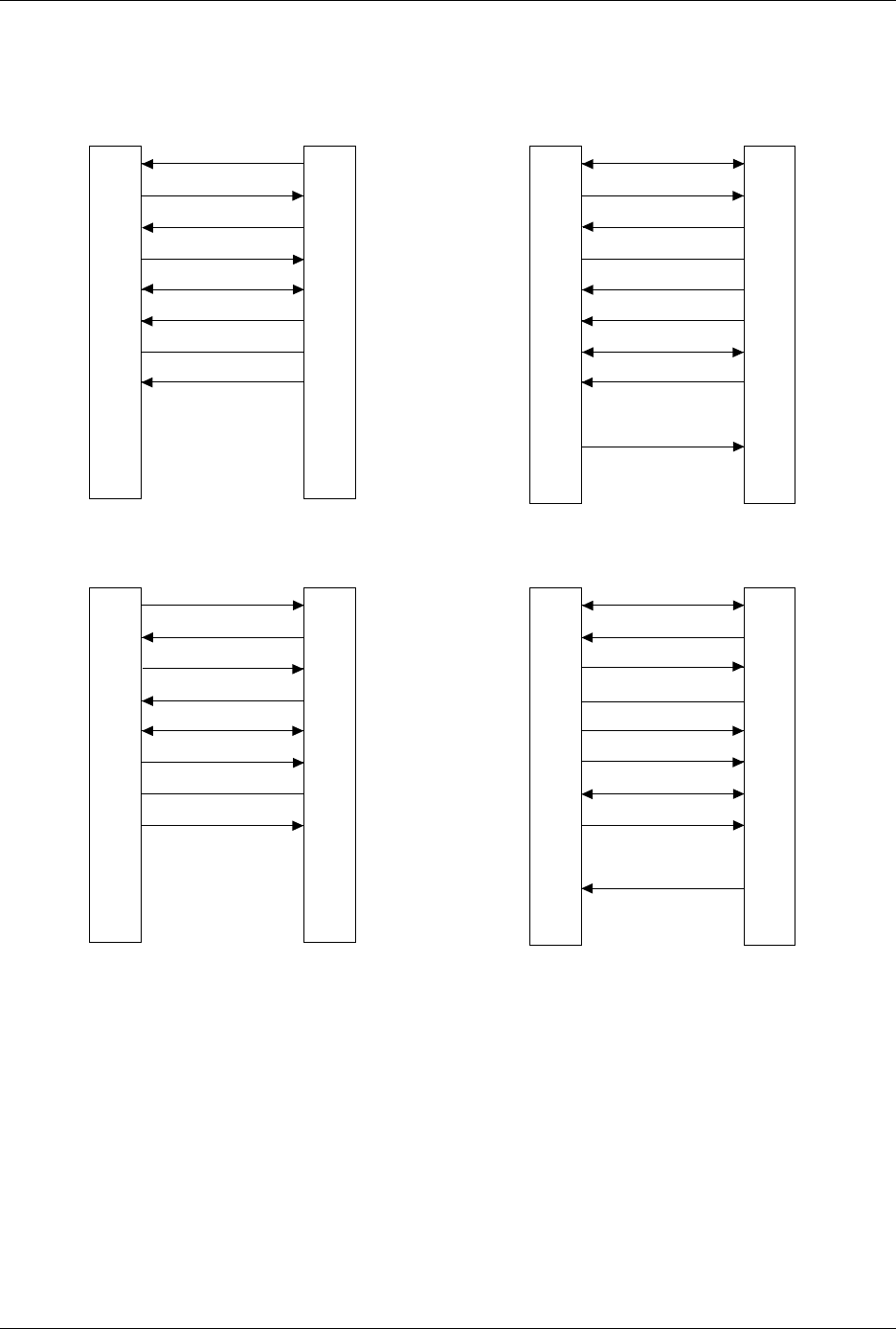
Figure 2-24
Pin Designations for RS-232C Serial Port Connection
1
2
3
4
5
6
7
8
9-19
20
21-25
1
2
3
4
5
6
7
8
20
PROTECTIVE GND
DATA
DATA
RTS (HELD HIGH)
CTS
DSR
SIGNAL GND
DCD
DTR
NC
GND
RECEIVE
TRANSMIT
RTS
CTS
DSR
GND
DCD
DTR
TRANSMIT
RECEIVE
25 PIN
AUTOSITE (DTE)
25 PIN
MODEM (DCE)
1
2
3
4
5
6
7
8
9-19
20
21-25
1
2
3
4
5
6
7
8
20
PROTECTIVE GND
DATA
DATA
RTS (HELD HIGH)
CTS
DSR
SIGNAL GND
DCD (HELD HIGH)
DTR
NC
NC
GND
TRANSMIT
RECEIVE
RTS
CTS
DSR
GND
DCD
DTR
RECEIVE
TRANSMIT
25 PIN
AUTOSITE (DCE)
25 PIN
TERMINAL (DTE)
1373-1
The minimum hookup includes Pins 2, 3, and 7.
Pins 1 and 7 are tied together.
NC
8
2
3
20
7
6
4
5
1
9-19
21-25
1
2
3
4
5
6
7
8
9
DCD
DATA
DATA
DTR
SIGNAL GND
DSR
RTS (HELD HIGH)
CTS
DCD
RECEIVE
TRANSMIT
DTR
GND
DSR
RTS
CTS
TRANSMIT
RECEIVE
25 PIN
AUTOSITE (DTE)
9 PIN
MODEM (DCE)
NC
NC
NC
8
2
3
20
7
6
4
5
1
9-19
21-25
1
2
3
4
5
6
7
8
9
DCD
DATA
DATA
DTR
SIGNAL GND
DSR
RTS (HELD HIGH)
CTS
DCD
TRANSMIT
RECEIVE
DTR
GND
DSR
RTS
CTS
RECEIVE
TRANSMIT
25 PIN
AUTOSITE (DCE)
9 PIN
TERMINAL (DTE)
NC
NC
NC
NC
NC

AutoSite User Manual 3-1
Operation
This chapter describes how to perform various day-to-day procedures on
AutoSite, including the following:
• Starting AutoSite .....................................................................................3-2
• Changing a Programming Module.......................................................3-2
• Changing a Programming Module on a ProMaster 2000...........3-3
• Changing a Programming Module on a ProMaster 3000,
7000, or 7500......................................................................................3-8
• Inserting a DIP or PLCC Base..............................................................3-13
• Removing a Base....................................................................................3-15
• Inserting DIP Devices ..........................................................................3-16
• Using MatchBooks with PLCC Devices.............................................3-17
• Isolating Programming Problems.......................................................3-20
• Adding a New Programming Module to AutoSite..........................3-21
• Performing a Self-Test..........................................................................3-22
• Manipulating Keep Current Algorithm Files....................................3-24
3