Autosite_Users_Manual.pdf - 第63页
Operation AutoSite User Manual 3-5 7. As show n in Figu re 3-2, sli de the clam p ring onto th e pin driver head , securing the programming module in place. CAUTION: You may hav e to push down on the programmi ng module …
Operation
3-4 AutoSite User Manual
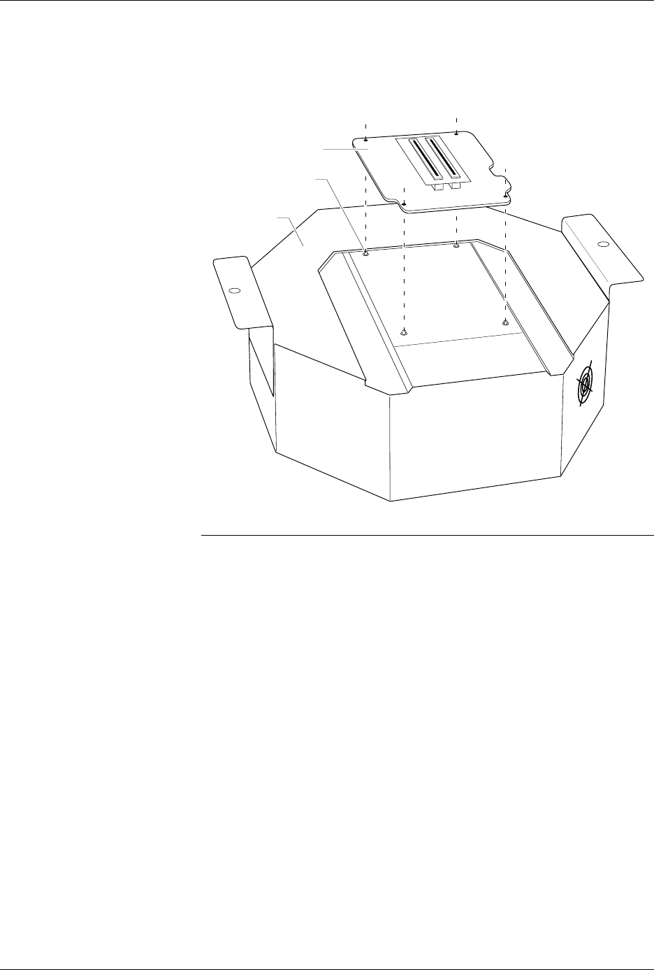
6. As shown in Figure 3-1, set the new programming module onto the
pin driver head, making sure the guide pins on the pin driver head
line up with the guide holes in the programming module.
Note: If you are using a programming module for the first time, and you
purchased the programming module after you purchased your AutoSite,
(i.e., you didn’t order the programming module and the AutoSite at the
same time) you must perform a one-time procedure to unlock the
programming module before you can use it.
Continue with the installation. At the appropriate time, a note in this
manual will tell you when to unlock the new programming module.
Figure 3-1
Aligning the Programming Module
on the Pin Driver Head
1350-1
PROGRAMMING
MODULE
PIN DRIVER
HEAD
GUIDE PIN (1 of 4)
Operation
AutoSite User Manual 3-5
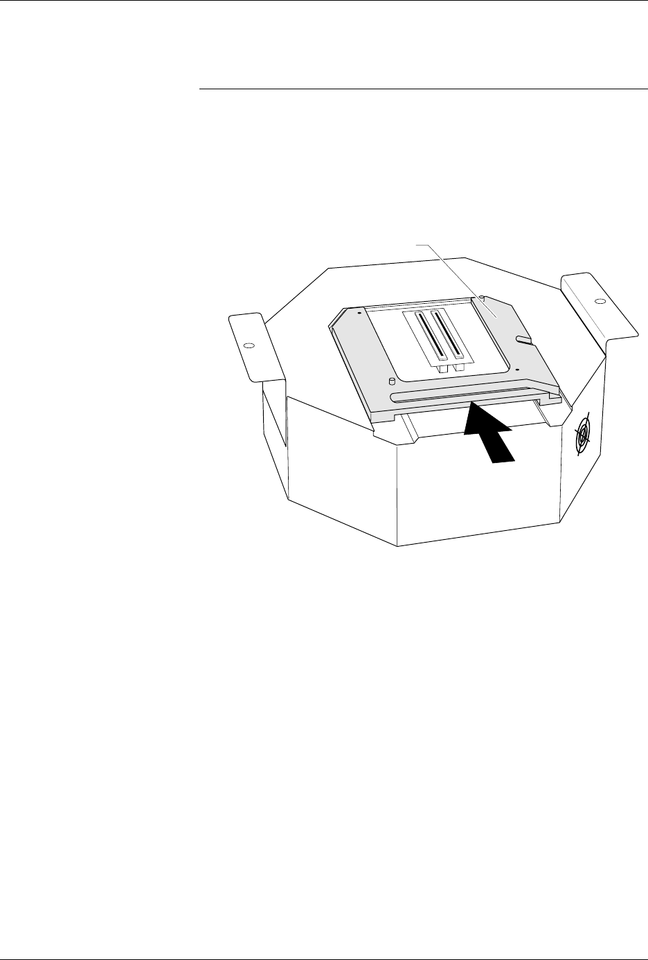
7. As shown in Figure 3-2, slide the clamp ring onto the pin driver head,
securing the programming module in place.
CAUTION: You may have to push down on the programming module
while sliding the clamp ring onto the pin driver head.
Do not use the device socket on the programming module as
a leverage point. You can damage the device socket by
applying any sort of force to it.
You will feel and hear a “click” from the clamp ring when the
programming module is properly secured to the pin driver head.
Figure 3-2
Securing a Programming Module
to the ProMaster 2000
1351-2
PROGRAMMING MODULE CLAMP RING
Operation
3-6 AutoSite User Manual
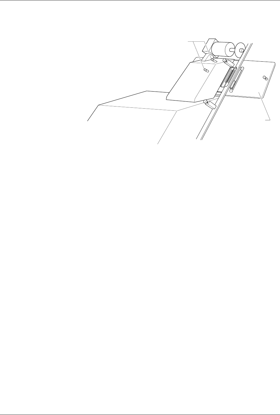
8. Remove the contactor set from the handler by loosening the two
thumbscrews shown in Figure 3-3. Set the contactor set aside.
9. Replace the old contactor set with the contactor set that matches the
programming module you installed in step 6. Position the pin driver
head mounting plate to the handler. Finger tighten the thumbscrews
on the handler to secure the pin driver head mounting plate to the
handler.
10. Position the pin driver head to the handler so that the handle on the
clamp ring is pointing toward the top of the handler.
11. As shown in Figure 3-4, align the card edge on the contactor set with
the card edge connectors on the programming module. Gently push
the pin driver head onto the handler.
Figure 3-3
Removing the Contactor Set from
the 2000
1346-1
CONTACTOR SET
THUMBSCREWS