Autosite_Users_Manual.pdf - 第65页
Operation AutoSite User Manual 3-7 12. Tighten the thum bscrews on the pin driver head mounting plate, securing the pin driver head to the handler. You might have to use a flatblade screwdriver to finish ti ghtening the …
Operation
3-6 AutoSite User Manual
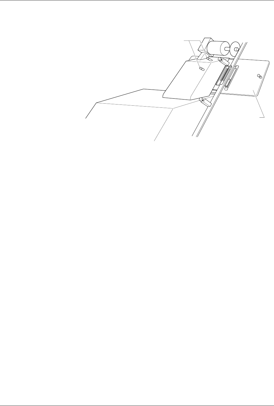
8. Remove the contactor set from the handler by loosening the two
thumbscrews shown in Figure 3-3. Set the contactor set aside.
9. Replace the old contactor set with the contactor set that matches the
programming module you installed in step 6. Position the pin driver
head mounting plate to the handler. Finger tighten the thumbscrews
on the handler to secure the pin driver head mounting plate to the
handler.
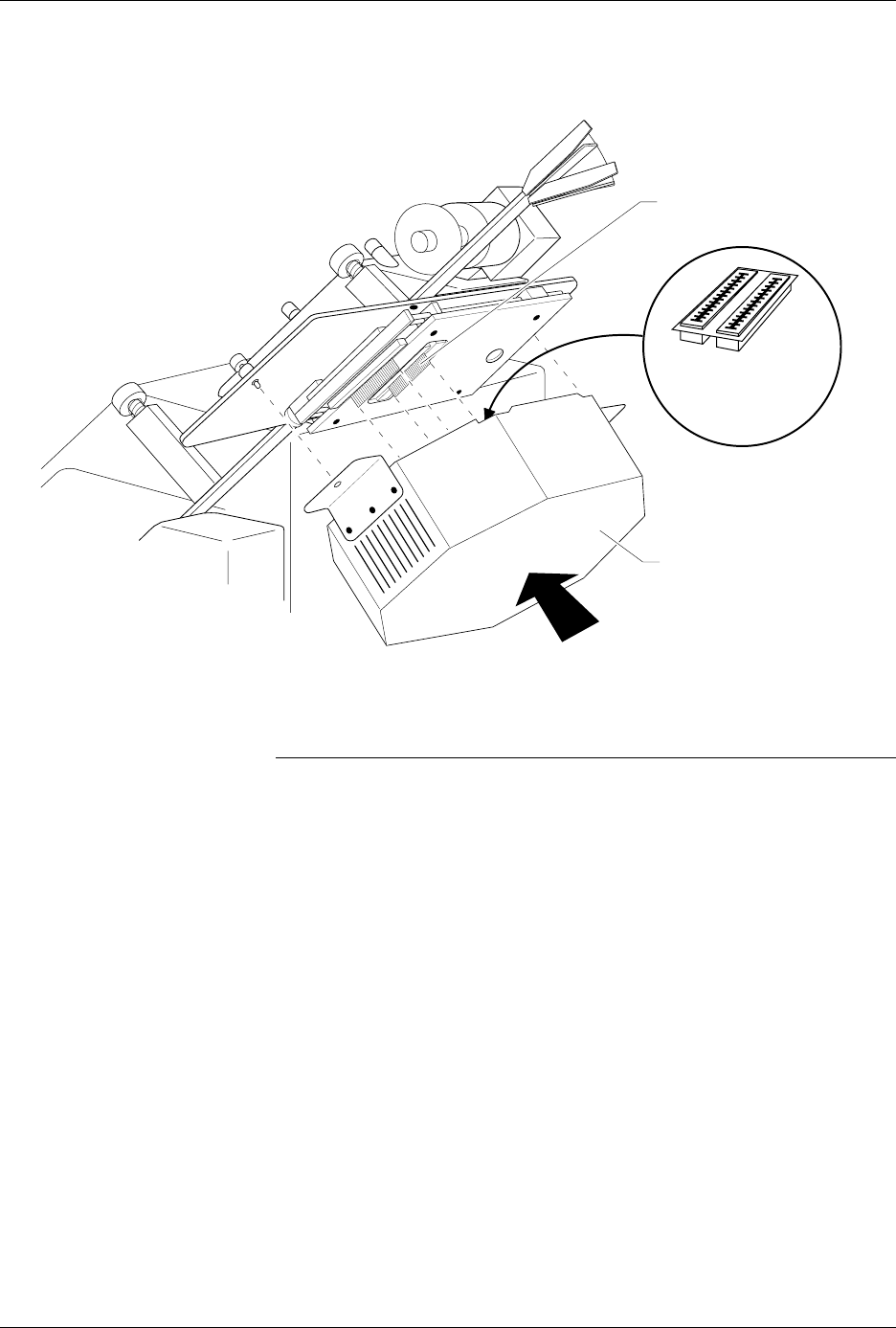
10. Position the pin driver head to the handler so that the handle on the
clamp ring is pointing toward the top of the handler.
11. As shown in Figure 3-4, align the card edge on the contactor set with
the card edge connectors on the programming module. Gently push
the pin driver head onto the handler.
Figure 3-3
Removing the Contactor Set from
the 2000
1346-1
CONTACTOR SET
THUMBSCREWS
Operation
AutoSite User Manual 3-7
12. Tighten the thumbscrews on the pin driver head mounting plate,
securing the pin driver head to the handler. You might have to use a
flatblade screwdriver to finish tightening the thumbscrews.
CAUTION: To prevent damage to the edge connectors, and to ensure
solid contact, we suggest you alternate tightening the left
and right thumbscrews until the pin driver head is
completely fastened to the 2000.
When properly connected to the handler, the mounting brackets attached
to the pin driver head will be flush against the pin driver head mounting
plate.
You are finished changing the programming module.
Figure 3-4
Aligning the Pin Driver Head with the 2000
1402-2
CARD EDGE ON
CONTACTOR SET
PIN DRIVER HEAD
(clamp ring toward top)
CARD EDGE
CONNECTORS ON
PROGRAMMING
MODULE

Operation
3-8 AutoSite User Manual
Changing a Programming Module on a ProMaster 3000,
7000, or 7500 Handler
Safety Information
This information is provided as a supplement to the Safety Summary at
the beginning of this manual.
The circuitry housed inside the pin driver head and the control unit and
the devices AutoSite programs are static sensitive and can be damaged by
electrostatic discharge (ESD). To help minimize the effects of ESD, we
suggest you wear an antistatic wrist strap while you follow the
procedures described in this section.
For best performance, the antistatic wrist strap should be connected to a
properly grounded antistatic workstation and the wrist strap should
contain a 1 M
Ω
(minimum) to 10 M
Ω
(maximum) isolating resistor.
Follow the steps below to change the programming module on a
ProMaster 3000, 7000, or 7500 handler. Instructions which pertain to a
specific handler are noted in the text.
1. Make sure the handler is idle.
2. Clear all devices from the handler.
3. Turn the knob on the control unit and push the control unit down so
you have more room to work (3000 and 7000 only).
CAUTION: In this section, you will be working with the control unit,
which is connected to the 3000. The control unit is supported
by an air shock and can spring up when you loosen the knob.
Use caution when adjusting the height of the control unit or
working with the air shock.
4. Raise the hood on the handler.