Autosite_Users_Manual.pdf - 第67页
Operation AutoSite User Manual 3-9 5. While using one hand to support the pin driver head, loosen the two thumb screws sh own in Figure 3-5 a nd lower the pin dri ver head from the handler. Set the pin driver head on the…

Operation
3-8 AutoSite User Manual
Changing a Programming Module on a ProMaster 3000,
7000, or 7500 Handler
Safety Information
This information is provided as a supplement to the Safety Summary at
the beginning of this manual.
The circuitry housed inside the pin driver head and the control unit and
the devices AutoSite programs are static sensitive and can be damaged by
electrostatic discharge (ESD). To help minimize the effects of ESD, we
suggest you wear an antistatic wrist strap while you follow the
procedures described in this section.
For best performance, the antistatic wrist strap should be connected to a
properly grounded antistatic workstation and the wrist strap should
contain a 1 M
Ω
(minimum) to 10 M
Ω
(maximum) isolating resistor.
Follow the steps below to change the programming module on a
ProMaster 3000, 7000, or 7500 handler. Instructions which pertain to a
specific handler are noted in the text.
1. Make sure the handler is idle.
2. Clear all devices from the handler.
3. Turn the knob on the control unit and push the control unit down so
you have more room to work (3000 and 7000 only).
CAUTION: In this section, you will be working with the control unit,
which is connected to the 3000. The control unit is supported
by an air shock and can spring up when you loosen the knob.
Use caution when adjusting the height of the control unit or
working with the air shock.
4. Raise the hood on the handler.
Operation
AutoSite User Manual 3-9
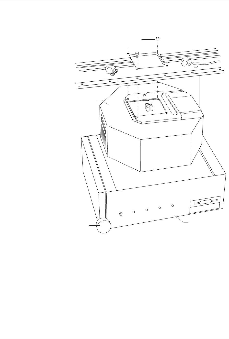
5. While using one hand to support the pin driver head, loosen the two
thumb screws shown in Figure 3-5 and lower the pin driver head
from the handler. Set the pin driver head on the control unit.
6. Slide the clamp ring off the pin driver head. Set the clamp ring aside;
you will need it later.
Figure 3-5
Removing the Pin Driver Head
from the Handler
1356-2
THUMBSCREW (1 of 2)
PIN DRIVER
HEAD
CONTROL UNIT
KNOB
POWER
AUXILIARY
HANDLER
SELF TEST
Operation
3-10 AutoSite User Manual
7. Remove the programming module from the pin driver head. Set the
programming module aside.
7500 only: Repeat this procedure for the second pin driver head.
CAUTION: Do not touch the pins that are exposed when you remove the
programming module.
Select the new programming module to be installed from the
Device List
disk, as described in your handler manual. If the module needs to have
the jumpers reconfigured, or if you are not certain how to determine if it
needs to be reconfigured, refer to the “Operation” chapter of your
handler manual.
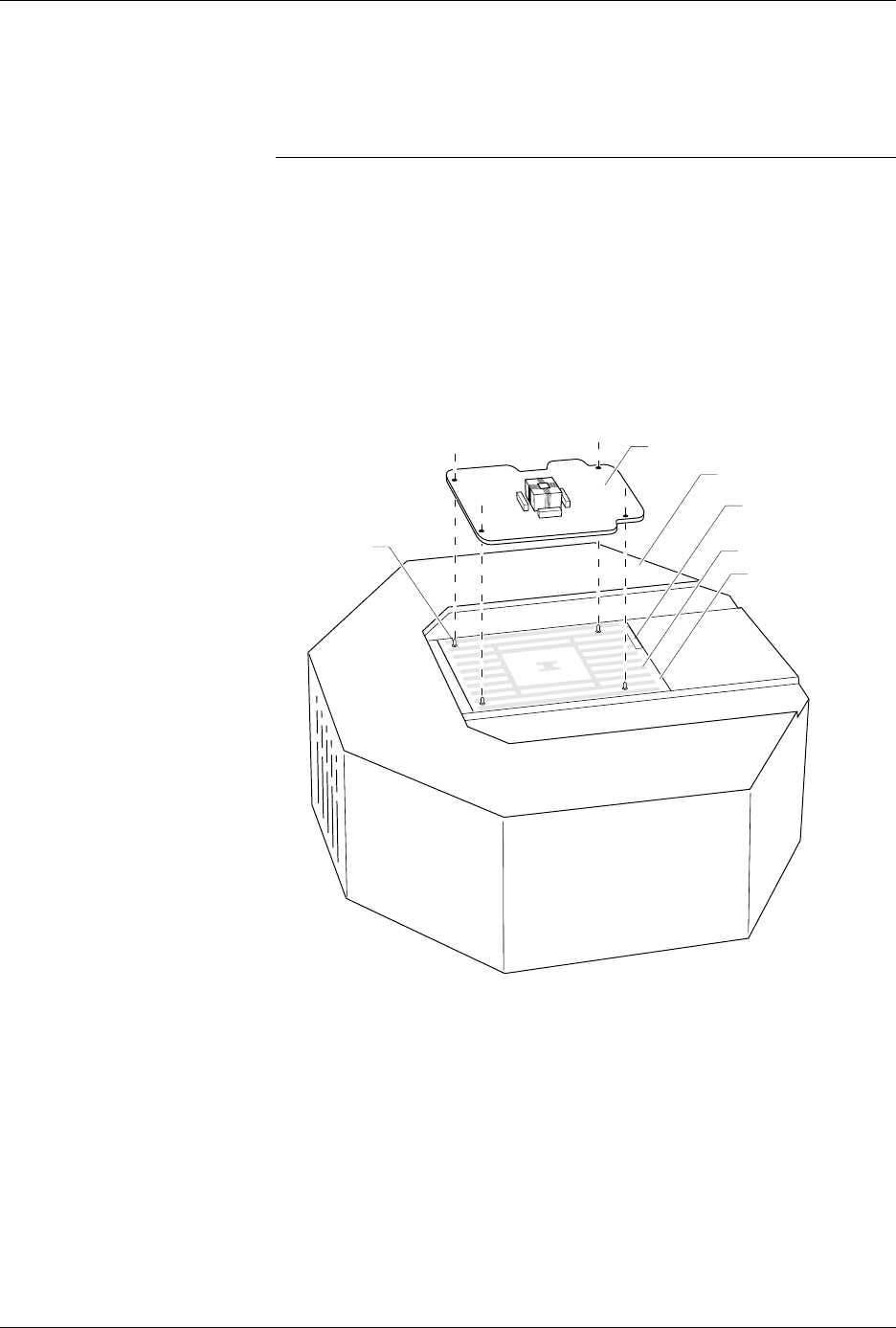
8. As shown in Figure 3-6, set the new programming module onto the
pin driver head, making sure the guide pins on the pin driver head
line up with the guide holes in the programming module.
Figure 3-6
Aligning the Programming Module
on the Pin Driver Head
1360-3
PROGRAMMING MODULE
GUIDE PIN
(1 of 4)
PIN DRIVER HEAD
SPA BLOCK
SQUIRT PINS
PART NUMBER
LABEL