Autosite_Users_Manual.pdf - 第69页
Operation AutoSite User Manual 3-11 9. As show n in Figu re 3-7, sli de the clam p ring onto th e pin driver head , secu ring the new pro grammin g mo dule in plac e. 7500 only: Install the module for the A utoSite. CAUT…
Operation
3-10 AutoSite User Manual
7. Remove the programming module from the pin driver head. Set the
programming module aside.
7500 only: Repeat this procedure for the second pin driver head.
CAUTION: Do not touch the pins that are exposed when you remove the
programming module.
Select the new programming module to be installed from the
Device List
disk, as described in your handler manual. If the module needs to have
the jumpers reconfigured, or if you are not certain how to determine if it
needs to be reconfigured, refer to the “Operation” chapter of your
handler manual.
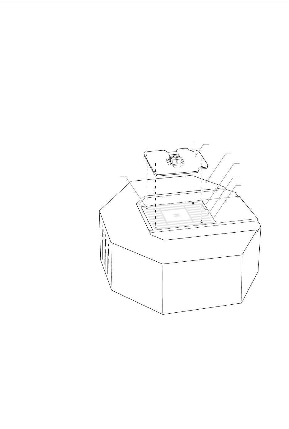
8. As shown in Figure 3-6, set the new programming module onto the
pin driver head, making sure the guide pins on the pin driver head
line up with the guide holes in the programming module.
Figure 3-6
Aligning the Programming Module
on the Pin Driver Head
1360-3
PROGRAMMING MODULE
GUIDE PIN
(1 of 4)
PIN DRIVER HEAD
SPA BLOCK
SQUIRT PINS
PART NUMBER
LABEL
Operation
AutoSite User Manual 3-11
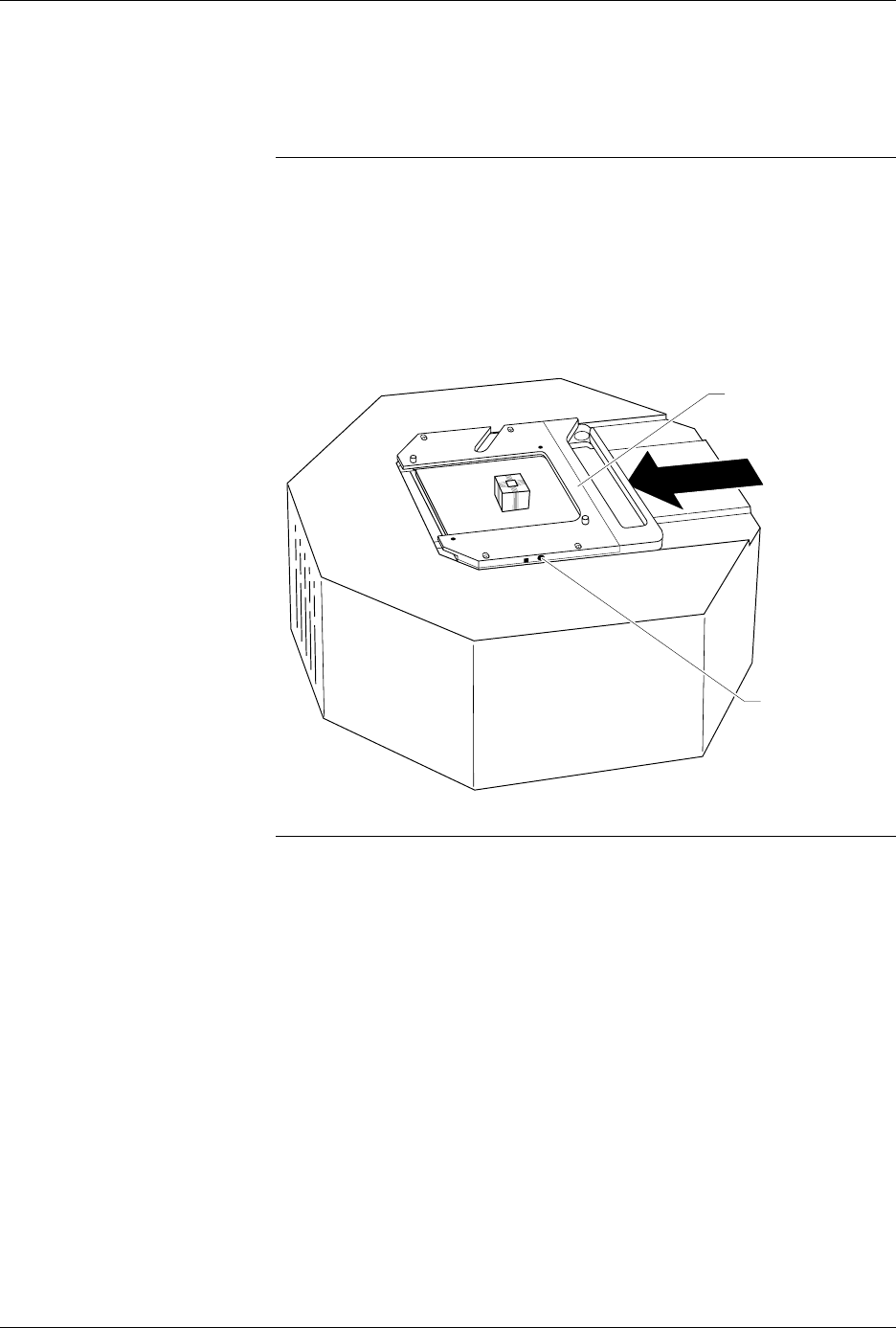
9. As shown in Figure 3-7, slide the clamp ring onto the pin driver head,
securing the new programming module in place.
7500 only: Install the module for the AutoSite.
CAUTION: To ensure good contact between the module and the spring
pins on the pin driver head, you may have to push down
slightly on the programming module while sliding the clamp
ring over the board. Apply downward pressure on the board,
not the programming module’s socket. Pressing down on the
socket could damage the pins or contacts.
You will feel and hear a “click” from the clamp ring when the
programming module is properly secured to the pin driver head.
Note: Before continuing with the next step, we suggest that you change the
chuck on the handler. See the “Removing and Installing Chucks” section
of the handler manual for more information.
Figure 3-7
Securing a Programming Module
to the Pin Driver Head
1361-2
PROGRAMMING
MODULE CLAMP RING
ADJUSTMENT
SCREW
Operation
3-12 AutoSite User Manual
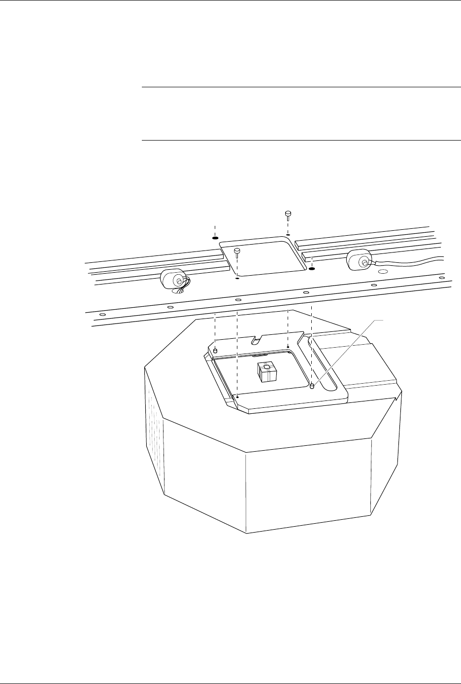
10. Position the pin driver head against the bottom of the handler. Using
the guide pins on the clamp ring, align the pin driver head with the
handler. Tighten the two thumbscrews to secure the pin driver head
to the handler.
Note: When properly connected to the handler, the clamp ring will be flush
against the handler.
7500 only: Replace the second pin driver head.
CAUTION: When the pin driver head is fully in position under the main
plate, make sure that no wires or air lines are pinched by the
head.
11. Readjust the height of the control unit (3000 and 7000 only).
You are finished changing the programming module.
Figure 3-8
Securing the Pin Driver Head to the Handler
1362-1
GUIDE PIN
(1 of 2)