Autosite_Users_Manual.pdf - 第74页
Operation 3-16 AutoSite User Manual Inserting a DIP Device To insert a DIP device in to the DIP Base, follow th e steps below: 1. Unlock the socket on the DIP Base by pulling up on the socket lever. 2. Insert the DIP dev…
Operation
AutoSite User Manual 3-15
Removing a Base
When removing a Base from AutoSite, be sure to apply even pressure
while moving the handles apart. If you exert uneven pressure on the
handles, you could damage the clamp ring.
To remove a Base, follow the steps described below.
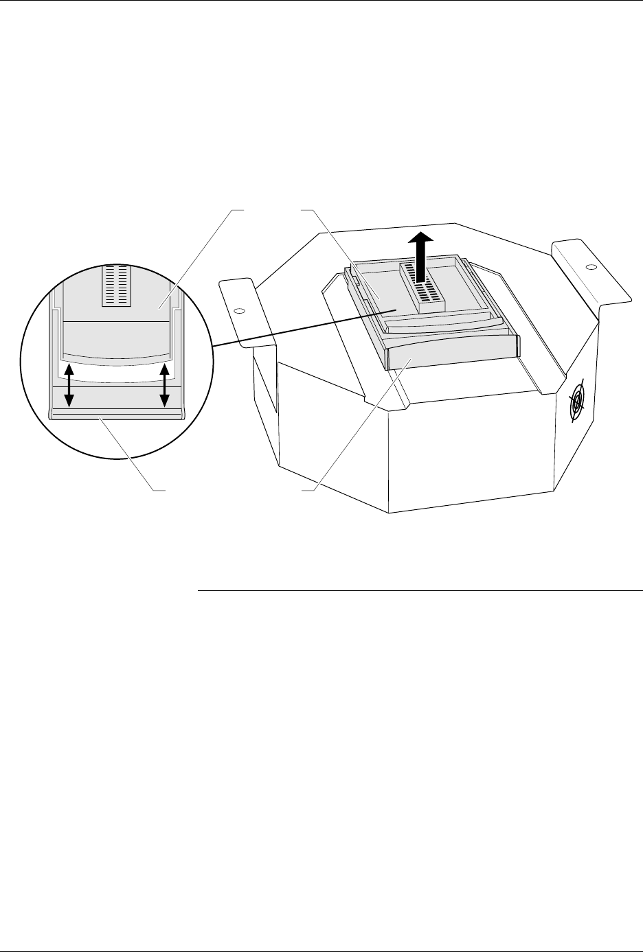
1. As shown in Figure 3-10, remove the Base by separating the handles
on the Base and the clamp ring with your thumbs and fingers.
2. Lift the Base up and out of the pin driver head. Store the Base in a safe
place.
CAUTION: Do not touch the pins that are exposed when you remove the
Base.
Once the Base is removed from AutoSite, we suggest you reinstall a
programming module in the pin driver head. For more information on
installing a programming module and reconnecting the pin driver head
to a handler, see the section titled “Changing a Programming Module”
earlier in this chapter.
Figure 3-10
Removing a Base
1380-2
DIP BASE
COMPRESSION HANDLE
Operation
3-16 AutoSite User Manual
Inserting a DIP
Device
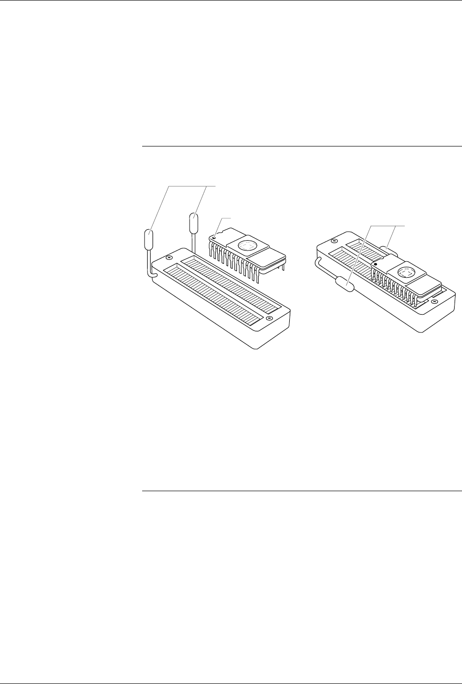
To insert a DIP device into the DIP Base, follow the steps below:
1. Unlock the socket on the DIP Base by pulling up on the socket lever.
2. Insert the DIP device into the socket. Make sure the device is bottom
justified. If the device is not bottom justified, AutoSite will not be able
to read or program the device.
3. Lock the device into place by pressing the socket lever down.
Note: Insert DIP devices into AutoSite AFTER you have installed the DIP Base
in AutoSite.
Removing a DIP
Device
To remove a DIP device from the DIP Base, follow the steps below:
1. Make sure AutoSite has finished programming and testing the device
in the DIP Base.
2. Unlock the socket on the DIP Base by pulling up on the socket lever.
3. Remove the device by lifting it out of the socket. Set the device on an
antistatic surface or in antistatic foam.
Note: Remove DIP devices from the DIP Base before you remove the DIP Base
from AutoSite.
Figure 3-11
Inserting a DIP Device into the
DIP Base
0548-1
SOCKET LEVERS
UNLOCKED
PIN 1
SOCKET
LEVERS
LOCKED
Operation
AutoSite User Manual 3-17
Inserting PLCC
Devices and Using
MatchBooks
Read this section if you will be using the Stand Alone Kit (a PLCC Base
and a set of MatchBooks) to program PLCC devices.
Data I/O has developed a new method to accommodate the special
nature of PLCC packages. The method uses the MatchBook, which holds
the PLCC device in place on the PLCC Base. When the device is locked
into place, the conductive pad on the bottom of the PLCC Base forms a
conductive path between the pin drivers in the pin driver head and the
device in the MatchBook.
MatchBooks do away with clumsy and expensive sockets and adapters,
and make inserting and removing surface mount devices much easier
and faster. MatchBooks eliminate the guesswork involved when you
insert a PLCC device into a socket. All you have to do is align pin 1 and
set the device in the MatchBook.
Inserting a Device Into a
MatchBook
The instructions below explain how to use a MatchBook and how to
insert and remove a device from a MatchBook.
1. Insert the PLCC Base into AutoSite. Lock the Base into place. See the
section titled “Inserting the DIP or PLCC Base” for information on
inserting the PLCC Base.
2. Select the MatchBook for the device you are going to use.
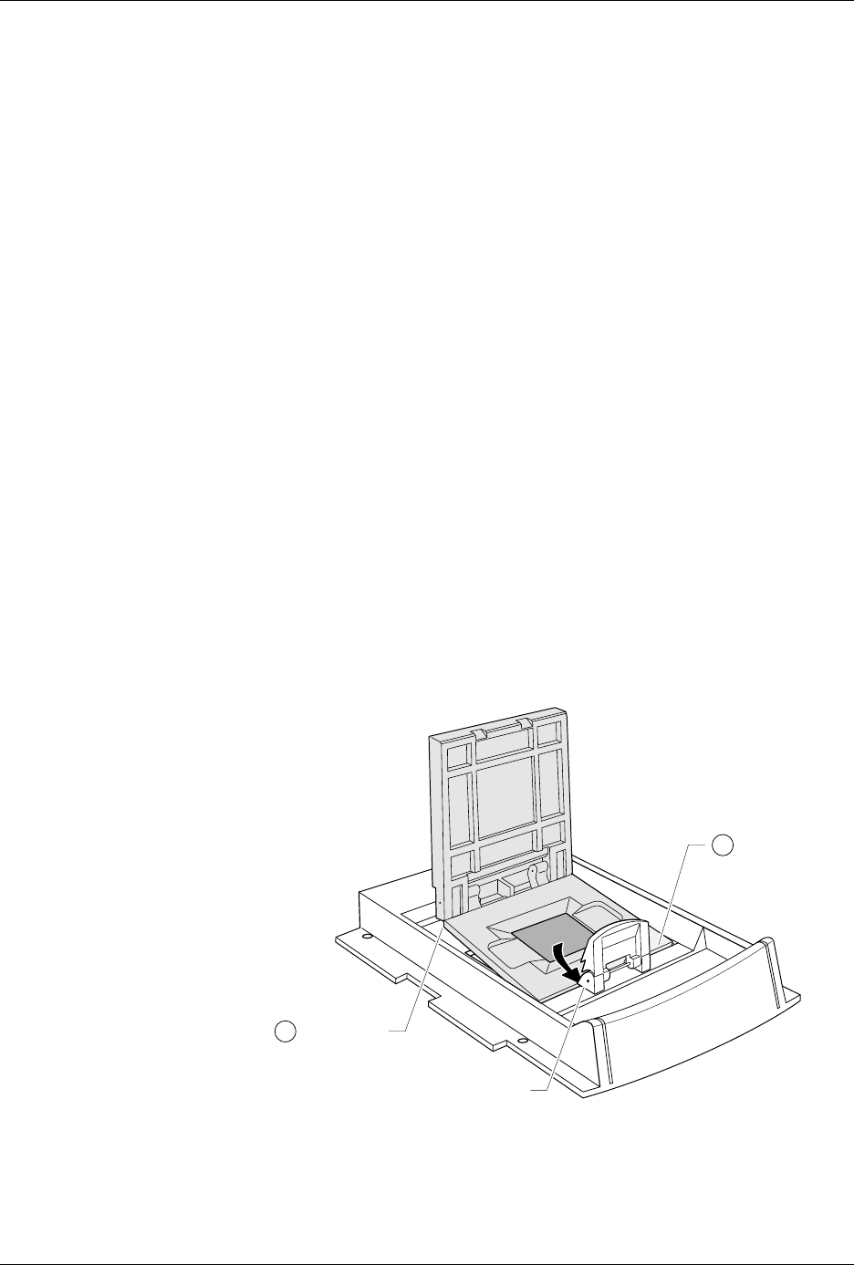
3. Insert the MatchBook into the PLCC Base as shown in Figure 3-12.
First, set the front edge of the MatchBook onto the PLCC Base. Then
lower the back edge of the MatchBook into place on the Base.
Figure 3-12
Inserting a MatchBook into the
PLCC Base
0537-3
2
1
FRONT EDGE
(under locking
tabs)
BACK EDGE
LOCKING TAB