00193889-0302_AI_LP-Ausrichtung_DE+EN.pdf - 第24页
LP-Ausrichtung SIPLACE S-27 HM / HS-60 / HF-Serie / X-Serie / D-Ser ie Ausgabe 11/2006 22 Fixierband einstellen 1 Klemmung Fixierband links rechts Bandende zum S p annen in Pfeilrichtung ziehen Fixierband nach außen stel…
LP-Ausrichtung SIPLACE S-27 HM / HS-60 / HF-Serie / X-Serie / D-Serie
Ausgabe 11/2006
21
: Kalibrieren Sie die LP-Referenz-Ecke (Bestücknest).
1
Dieser Vorgang muss auch nach Ausbau der Option wiederholt werden. 1
1
1.6 Fehlerbehebung HS-60
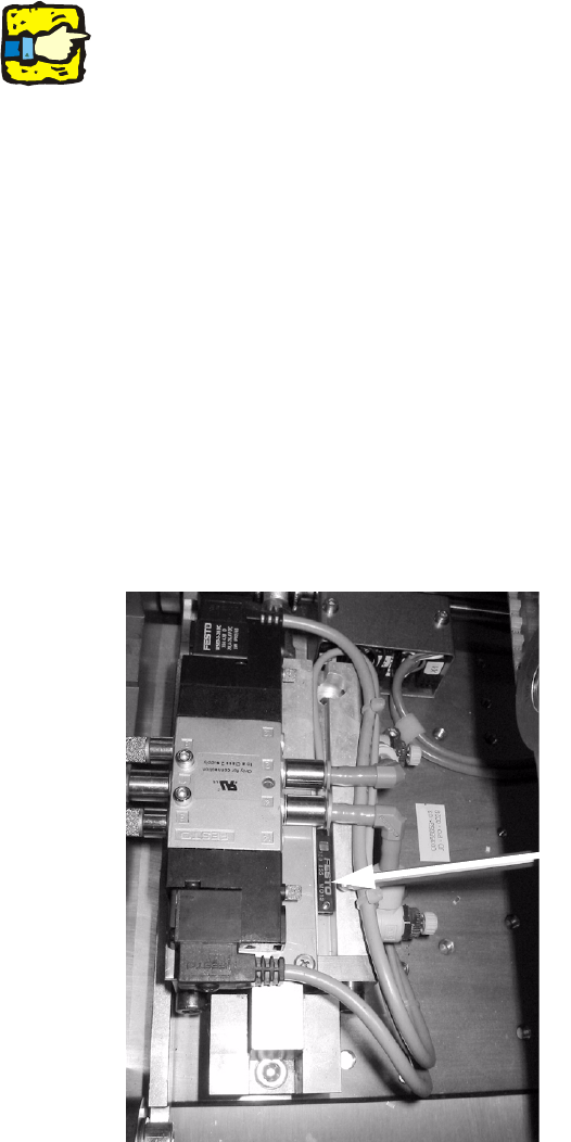
Endschalter ‘Hubtisch unten’ 1
Durch die Unterlegscheiben im Hubtisch kann es vorkom
men, dass der Endschalter ‘Hubtisch un-
ten’ nicht anspricht. Gehen Sie in diesem Fall folgendermaßen vor: 1
: Demontieren Sie die Hubtischplatte
: Markieren Sie die Position des induktiven Nä
herungsschalters (für spätere Rückrüstung).
: Verschieben Sie nun den Schalter gegen die Tra
nsportrichtung bis er anspricht (die LED
leuchtet).
induktiver
Näherungsschalter
1
Abb. 1 - 1 Hubtischzylinder und Näherungsschalter
1
1
1
LP-Ausrichtung SIPLACE S-27 HM / HS-60 / HF-Serie / X-Serie / D-Serie
Ausgabe 11/2006
22
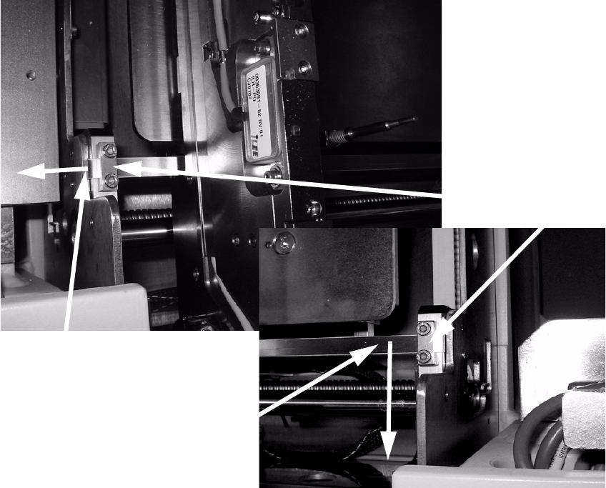
Fixierband einstellen 1
Klemmung Fixierband
links rechts
Bandende
zum Spannen in
Pfeilrichtung ziehen
Fixierband nach außen
stellen
(in Pfeilrichtung ziehen)
1
Abb. 1 - 2 Fixierband Transportbreiten-Verstellung HS-60
: Sollte ‘Anschlag LP-Ausrichtung’ im Bearbeitungsbereich 2 am Fixierband schleifen, lösen Sie
die Klemmungen auf beiden Seiten und stellen Sie das Fixierband soweit wie möglich nach
außen (siehe Bild oben).
: Achten Sie darauf, dass das Fixier
band ausreichend Spannung hat:
Spannen Sie ggf. das Fixierband nach, indem Sie die Klemmung lösen und mit einer Zange
am
Bandende ziehen (siehe Bild ganz oben).
1
PCB alignment unit for SIPLACE S-27 HM / HS-60 / HF-series / X-series / D-series
Edition 11/2006
23
2 Assembly instructions
PCB alignment unit
These instructions describe how to install the following PCB alignment units: 2
00118526-01 / 00118525-01 / 00119426-01 / 00119425-01 / 00119678-01 / 00119677-01 /
0
0119858-01 / 00119857-01. 2
2.1 Overview
This option is an additional mechanical stopper that may be needed for: 2
– PCB’s with a aspect ratio of 1:2 (length/width) or shorter
If PCB’s in landscape format (with the short side in moving direction) runs through the machine,
they
have too little lateral guidance and so they can twist a little. 2
This option aligns all PCB’s so that PCB fiducials are always
visible in the search window of the
PCB vision camera. 2
– For PCBs with cut-outs in moving direction:
On PCB conveyors for the existing machine platform, the mechanical stopper (HS-50 / S-25 HM
/ F
5 HM) stops the PCB in a different position than on the new conveyor with laser light barrier
(HS-60 / S-27 HM / HF-series / X-series / D-series). 2
This option ensures that PCB with recesses in moving
direction are always stopped exactly on the
same position on different PCB conveyor systems. 2
2.2 Description of the functions
The PCB is transported into the placement area until the laser light barrier is activated and the
PCB stops. As the first PCB moves in, the lifting table performs a reference run that determines
the PCB thickness. The lifting table then moves up until the PCB is still able to move with the
conveyor belt, and the ‘stopper PCB adjustment’ is level with the PCB. The PCB is then moved
with the conveyor belts against the PCB alignment unit, where it is aligned. Finally, the lifting table
is moved up so that the PCB is clamped and not in contact with the PCB alignment unit. 2
Once the placement process is complete, the lifting table moves the PCB alignment unit and the
PCB
down until the PCB can be moved onwards without interruption. 2