00193889-0302_AI_LP-Ausrichtung_DE+EN.pdf - 第32页
PCB alignment unit for SIPLACE S-27 HM / HS-60 / HF-series / X-ser ies / D-series Edition 11/2006 30 2.5 Retrofit : Set the conv eyor width to 200 mm. : Switch the placement mach ine off at the main switch. : Move the ga…

PCB alignment unit for SIPLACE S-27 HM / HS-60 / HF-series / X-series / D-series
Edition 11/2006
29
2.4 Safety instructions
WARNING 2
Comply with the higher ranking "Safety Instructions" in Chapter "Operational Safety" in the User
Manual and Service Manual. 2
The placement machines SIPLACE are powered by mains voltage.
Portions of the system are therefore conducting da
ngerous electricity, inside the machine even
while the master switch is turned off.
Death, serious injury or considerable damage may result if these automatic placement systems
a
re handled incorrectly.
After you have properly carried out the shut-
down of the operating system:
Before all work the machine must be turned off at the
main switch and isolated from the mains. In
addition, the compressed air supply must be turned off at the main valve of the compressed air
unit in the machine base and the compressed air lines must be bled by actuating the needle valve
at the compressed air unit.
Danger: For anyone wearing a heart pacemaker it is not permitted to work near linear motors, as
d
escribed in detail in the User Manual and the Service Manual, Chapter "Special Safety
Instructions when working in vivinty of powerful magnetic fields" .
Obey the applicable accident prevention regulations, DIN
standards and special safety codes of
your country at all times. DIN EN 60204 must be adhered to during all work inside the machine
base.
Follow the instructions regarding residual voltages in Chapter "Operational Safety".
Comply with regulations on ESDs (see Chapter "Operational Safety").
During the work of retrofitting secure the machine conscientiously against other personnel and
p
revent it from being turned back on without authorization, as described in the User Manual in the
chapter "Locking the Machine...".
There is additional, higher risk of accident when working with the SITEST program.
The SITEST program is only to be started by personnel who are authorized to do so. 2
2
2.4.1 Definitions
2
Please note
2
2
2
Caution
2
PCB alignment unit for SIPLACE S-27 HM / HS-60 / HF-series / X-series / D-series
Edition 11/2006
30
2.5 Retrofit
: Set the conveyor width to 200 mm.
: Switch the placement machine off at the main switch.
: Move the gantry over the pick-up area.
: Unscrew the four screws to remove the lifting table bed.
2
2
The following modules only have to be fitted in the HS-60 / D4: 2
2
: Unscrew the plastic springs on the right and left of the lifting table bed.
: Place a 3 mm plain washer beneath each spring and then screw in once more.
Plastic spring
Plain washer 3 mm
DIN 7349
Plastic spring
Plain washer 3 mm
DIN 7349
2
2
PCB alignment unit for SIPLACE S-27 HM / HS-60 / HF-series / X-series / D-series
Edition 11/2006
31
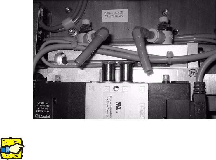
: Vent the lifting table cylinders in placement area 2 by detaching the two air hoses. This will
make it easier to subsequently fit the path limiter.
2
2
2
The following procedure has to be done on each machine type:
2
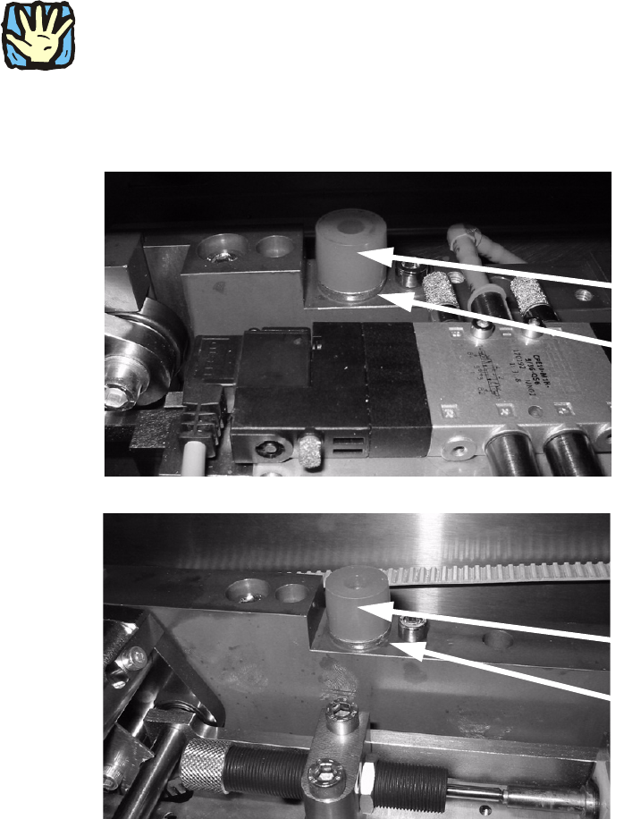
Fitting the ‘path limiter slat’ 2
This slat limits the free moving space from ‘stopp
er PCB adjustment’ to the top. 2
2
Some types of machine and placement areas require different path limiters: 2
S-27 HM:
PA1: Fix module with spacer (61 mm) Item no. 00366561-xx 2
HS-60 / D4:
PA1: Fix module with block (30 mm) Item no. 00366480-xx
PA2: Fix module with block (14 mm) Item no. 00366478-xx 2
HF-series / X-series / D3:
PA1: Fix module with spacer (55 mm) Item no. 00371982-xx
PA2: Fix module with spacer (71 mm) Item no. 00371983-xx 2
D1 / D2:
PA1: Fix module with spacer (60 mm) Item no. 03053481-xx
2
2