00193889-0302_AI_LP-Ausrichtung_DE+EN.pdf - 第34页
PCB alignment unit for SIPLACE S-27 HM / HS-60 / HF-series / X-ser ies / D-series Edition 11/2006 32 : Disassembly the lifting t able. : Fix the block/spa cer colocate with ‘p ath limiter slat ’ on the end face of the li…
PCB alignment unit for SIPLACE S-27 HM / HS-60 / HF-series / X-series / D-series
Edition 11/2006
31
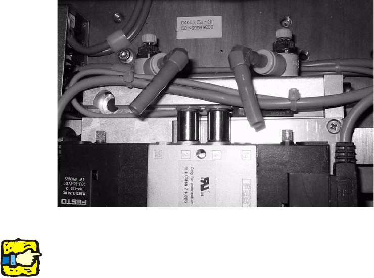
: Vent the lifting table cylinders in placement area 2 by detaching the two air hoses. This will
make it easier to subsequently fit the path limiter.
2
2
2
The following procedure has to be done on each machine type:
2
Fitting the ‘path limiter slat’ 2
This slat limits the free moving space from ‘stopp
er PCB adjustment’ to the top. 2
2
Some types of machine and placement areas require different path limiters: 2
S-27 HM:
PA1: Fix module with spacer (61 mm) Item no. 00366561-xx 2
HS-60 / D4:
PA1: Fix module with block (30 mm) Item no. 00366480-xx
PA2: Fix module with block (14 mm) Item no. 00366478-xx 2
HF-series / X-series / D3:
PA1: Fix module with spacer (55 mm) Item no. 00371982-xx
PA2: Fix module with spacer (71 mm) Item no. 00371983-xx 2
D1 / D2:
PA1: Fix module with spacer (60 mm) Item no. 03053481-xx
2
2
PCB alignment unit for SIPLACE S-27 HM / HS-60 / HF-series / X-series / D-series
Edition 11/2006
32
: Disassembly the lifting table.
: Fix the block/spacer colocate with ‘path limiter slat
’ on the end face of the lifting table.
2
On S-27 HM, this path limiter is L-shaped.
Fit it with the longer limb at the top. 2
Hole for path limiter
Fitted path limiter
2
2
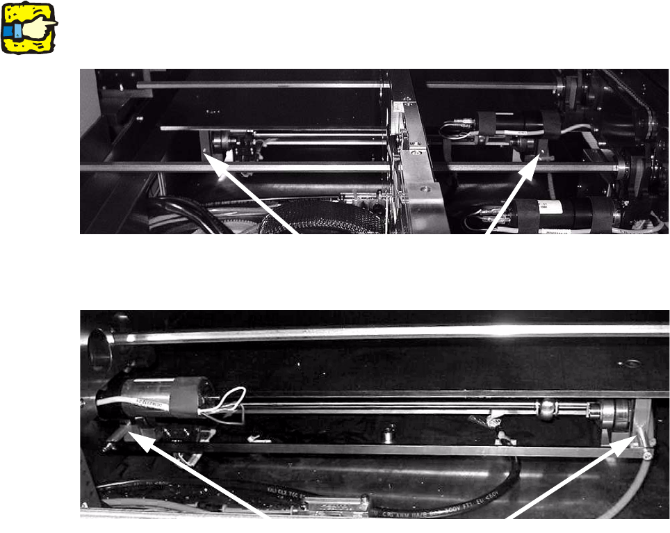
Fig. 2 - 1 Sample picture from HS-60 placement area 1 (similar to other conveyor types)
Fitted spacer and
‘path limiter slat’
Threaded hole
PCB alignment unit for SIPLACE S-27 HM / HS-60 / HF-series / X-series / D-series
Edition 11/2006
33
2
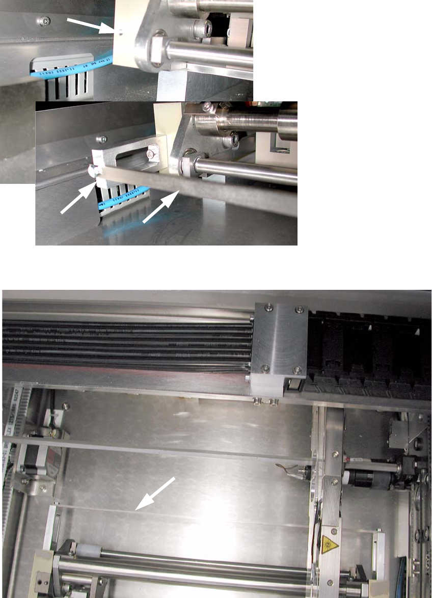
Fig. 2 - 2 Fitted path limiter by example for D1 / D2
2
Fig. 2 - 3 Top view on ‘path limiter slat’ e.g. D1 / D2