00193889-0302_AI_LP-Ausrichtung_DE+EN.pdf - 第40页
PCB alignment unit for SIPLACE S-27 HM / HS-60 / HF-series / X-ser ies / D-series Edition 11/2006 38 2 Fig. 2 - 12 Example of a coding switch from D1 / D2 The coding switch allows the operator to d eterm ine whether the …
PCB alignment unit for SIPLACE S-27 HM / HS-60 / HF-series / X-series / D-series
Edition 11/2006
37
2
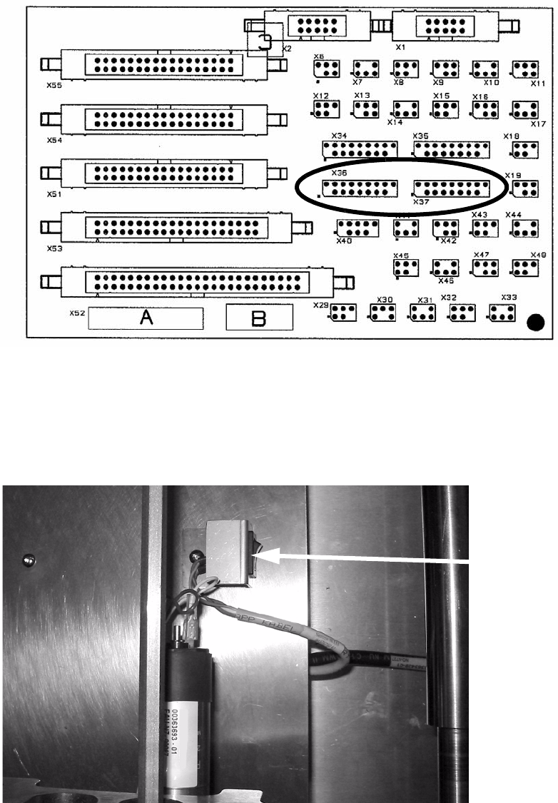
Fig. 2 - 10 Conversion board HS-60 / HF / D3 / D4 (00359425-)
: Carry the cables along the ribbon cable (see Fig. 2 - 11 and Fig. 2 - 12).
: Put the cover plate on it.
: Add the coding switch to the cover plate and fix both.
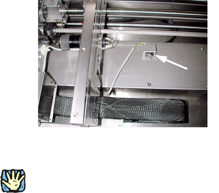
Fig. 2 - 11 Example of a coding switch from HS-60, other conveyors are similar
Coding switch
PCB alignment unit for SIPLACE S-27 HM / HS-60 / HF-series / X-series / D-series
Edition 11/2006
38
2
Fig. 2 - 12 Example of a coding switch from D1 / D2
The coding switch allows the operator to determine whether the PCB alignment option should be
used or not. 2
2
If the option is disabled, the ‘stopper PCB adjustment’ must be removed since, in this case, the
conveyor control will not detect the stop, which could result in a crash when the conveyor side
walls are moved. 2
If this switch is active, a warning is displaye
d on screen as they move together: 2
Transport error: 15429 Warning: Conveyor
belt moving together with installed option—Pick-up
side: Conv. EC:8
Wait for handling data 2
: Fit the lifting table bed in the conveyor once more.
2
PCB alignment unit for SIPLACE S-27 HM / HS-60 / HF-series / X-series / D-series
Edition 11/2006
39
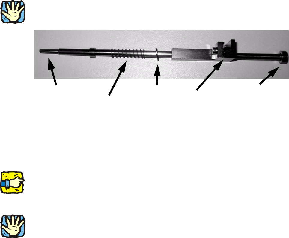
Mounting the ‘stopper PCB adjustment’: 2
2
With S-27 HM are used shorter (148 mm) ‘stopper PCB adjustments’ (00366392-). By application
of other ‘stopper PCB adjustments’ it could result in a crash. 2
Stop washer
bottom
Wedge
Plain washer
Compression spring (prevents PCB damage)
PCB stop
2
Fig. 2 - 13 ‘Stopper PCB adjustment’
: Thread the stop washer ‘stopper PCB adjustment’ beneath the ‘path limiter slat’ (see Fig. 2 -
15).
: Clamp the ‘stopper PCB adjustment’ loos
ely on the lifting table.
: Switch the ‘stopper PCB adjustment’—matching with you
r PCB—in the final position and fix it.
2
When the ‘stopper PCB adjustment’ is pulled up, it should slide down without hitting the ‘path
limiter slat’.
2
: Make sure that the ‘stopper PCB adjustment’ is not cover the ‘path limiter slat’.
2
HS-60: By moving, the ‘stopper PCB adjustment’ must not cover the fixing belt!
(Only the fixing belt of HS-60 is in the immediate vicinity.) 2
2
: Check that the lifting table and lifting table rockers can be moved up freely. If the plain washer
of the ‘stopper PCB adjustment’ is in contact with the width adjustment fixing belt, you have to
eliminate it (see Troubleshooting page 41).
: Check that the width adjusting unit moves fr
ee
ly over the entire conveyor width.