00196504-02_UM_X-Serie_SR70X_EN.pdf - 第123页
User manual SIPLACE X-series Technical data for the machine From software version SR.70x.x x 01/2011 EN edition Placement head 123 3.5 Placement head 3.5.1 SIPLACE SpeedS tar fo r very high-speed placement 3 Fig. 3.5 - 1…
Technical data for the machine User manual SIPLACE X-series
Overview of the modules From software version SR.70x.xx 01/2011 EN edition
122
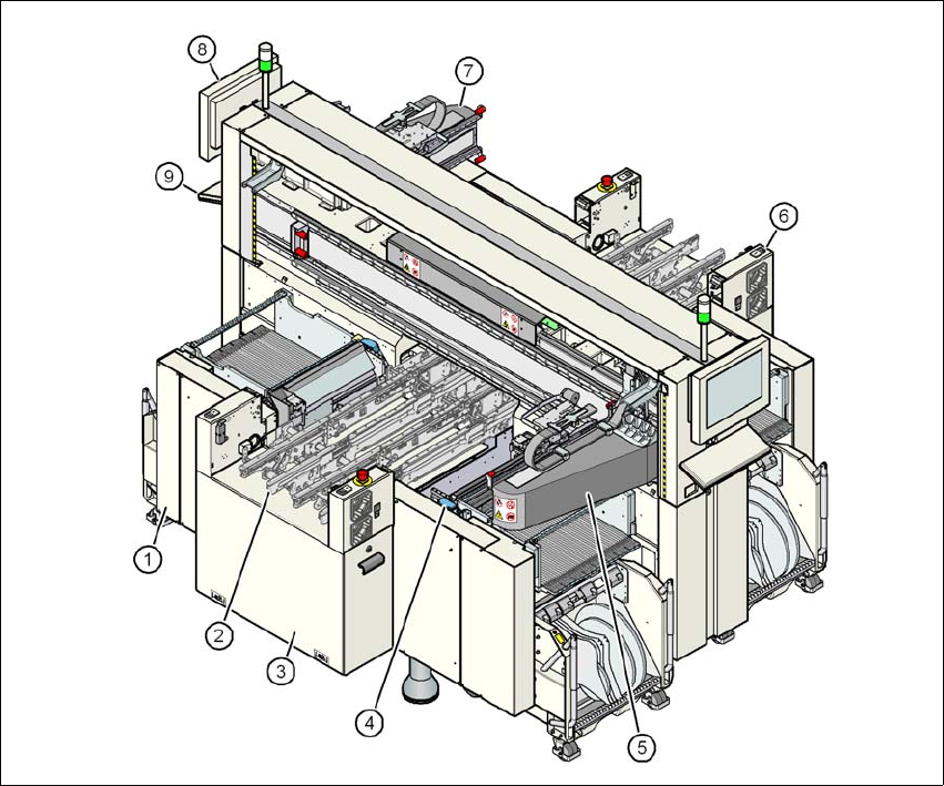
3.4.4 Overview of the modules SIPLACE X2
3
Fig. 3.4 - 4 X2 machine - overview of the modules
(1) Machine frame
(2) PCB conveyor (flexible dual conveyor)
(3) Extension kit on the PCB input side
(4) Component trolley docking unit, tape cutter, used tape channel (4x)
(5) Gantry 1 with placement head
(6) Extension kit on the PCB output side
(7) Gantry 3 with placement head
(8) Monitor (2x)
(9) Keyboard (2x)
User manual SIPLACE X-series Technical data for the machine
From software version SR.70x.xx 01/2011 EN edition Placement head
123
3.5 Placement head
3.5.1 SIPLACE SpeedStar for very high-speed placement
3
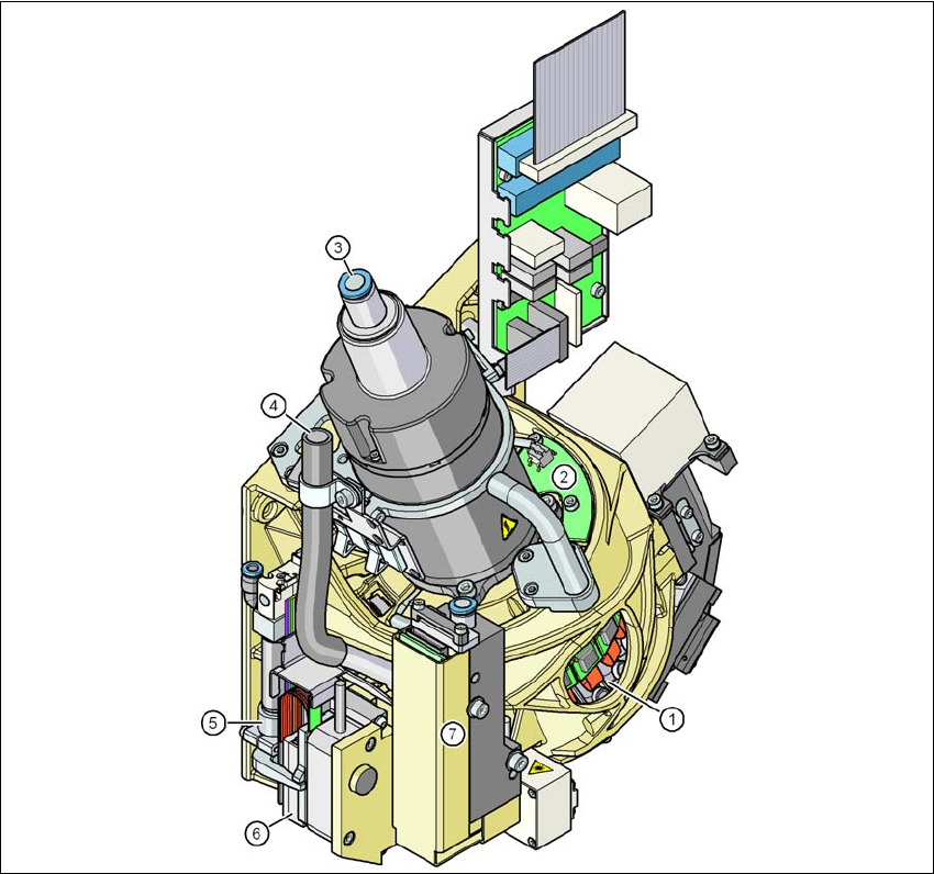
Fig. 3.5 - 1 SIPLACE SpeedStar - Function groups, part 1
(1) DP drive, 20 drives
(2) "Vacuum sensor holding circuit" board
(3) Compressed air connection for 20 Venturi nozzles in the pick-up/placement and holding cir-
cuit
(4) Line for the exhaust air from the pressure control valve (7)
(5) Return cylinder
(6) Z motor (linear motor)
Technical data for the machine User manual SIPLACE X-series
Placement head From software version SR.70x.xx 01/2011 EN edition
124
(7) Pressure control valve
3
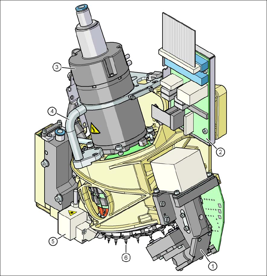
Fig. 3.5 - 2 SIPLACE SpeedStar - Function groups, part 2
(1) C&P component camera, type 23, 6 x 6, digital
(2) Intermediate distributor board
(3) Star motor
(4) Handle
(5) Component sensor
(6) Star with 20 nozzles