00196504-02_UM_X-Serie_SR70X_EN.pdf - 第125页
User manual SIPLACE X-series Technical data for the machine From software version SR.70x.x x 01/2011 EN edition Placement head 125 3.5.1.1 Description The SIPLACE SpeedSt ar(C&P20) works on the Collect&Plac e pri…
Technical data for the machine User manual SIPLACE X-series
Placement head From software version SR.70x.xx 01/2011 EN edition
124
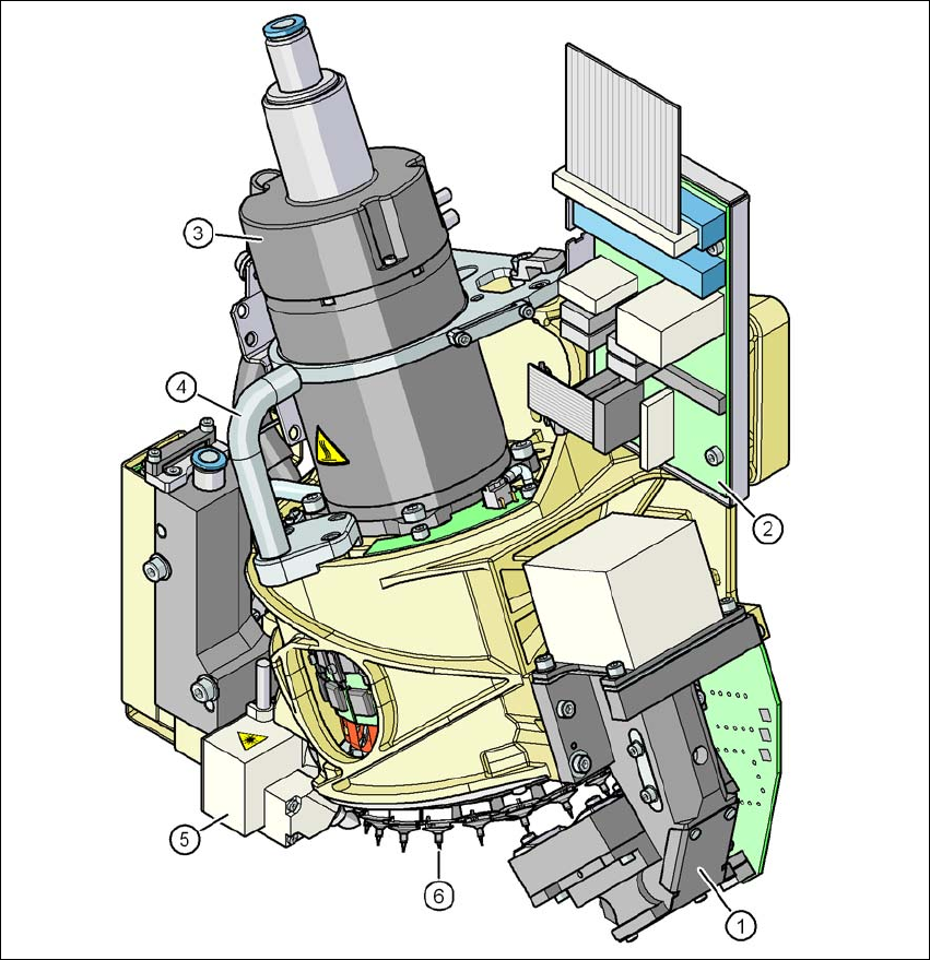
(7) Pressure control valve
3
Fig. 3.5 - 2 SIPLACE SpeedStar - Function groups, part 2
(1) C&P component camera, type 23, 6 x 6, digital
(2) Intermediate distributor board
(3) Star motor
(4) Handle
(5) Component sensor
(6) Star with 20 nozzles
User manual SIPLACE X-series Technical data for the machine
From software version SR.70x.xx 01/2011 EN edition Placement head
125
3.5.1.1 Description
The SIPLACE SpeedStar(C&P20) works on the Collect&Place principle. This means that, within
each cycle, twenty components are picked up by the placement head. At the pick-up and place-
ment position the component sensor checks that the component is present at the nozzle. On their
way to the placement position the components are optically centered and rotated into the required
placement angle. Finally forced air sets down the component gently and accurately on the board.
The C&P head succeeds in considerably increasing the output of the placement head and thus of
the overall placement machine. The compact construction of the C&P20 head allows very short
cycle times. In this case, the star axis is at an angle to the PCB level. This geometry allows the
segments to be arranged in a very small space.
The component camera is still integrated into the C&P20 head. This saves additional traveling
distances to external centering cameras. Each segment also has a separate DP drive for rotating
the nozzle. The nozzles are therefore no longer rotated into the correct position at a single head
station. They can be rotated into their placement position at any time and independently of one
another.
Each segment has a separate vacuum generator. This greatly reduces the time taken to switch
between vacuum and air kiss. It also allows a vacuum check to be carried out in the holding circuit
for each individual nozzle.
The Z drive for the segments is implemented with a linear motor with linear path measuring sys-
tem, and is thus extremely precise. In the pick-up/placement position, the Z drive moves the seg-
ments up or down in the vertical direction.

Technical data for the machine User manual SIPLACE X-series
Placement head From software version SR.70x.xx 01/2011 EN edition
126
3.5.1.2 Technical data
3
3
3
3
3.5.1.3 Sensor for the component reject bin
PLEASE NOTE 3
If a SpeedStar is used, then we recommend that you install the optional sensor for the compo-
nent reject bin. (See also Section 6.4, page 403)
Range of components
a
a) Please note that the component range that can be placed is also affected by the pad geometry, the cus-
tomer-specific standards and the packaging tolerances.
01005 to 2220, Melf, SOT, SOD
Component specification
max. height
min. lead pitch
min. lead width
min. ball pitch
min. ball diameter
min. dimensions
max. dimensions
max. weight
4 mm
0.25 mm
0.1 mm
0.4 mm
0.2 mm
0.4 x 0.2 mm²
6 x 6 mm²
1 g
Programmable set-down force, variable increments 1.5 ± 0.5 N
2.0 ± 0.5 N
3.5 ± 1 N
4.5 ± 1 N
Nozzle types 10xx, 11xx, 12xx
X/Y accuracy
b
b) The accuracy value was measured using the vendor-neutral IPC standard.
± 41 μm/3, ± 55 μm/4
Angular accuracy ± 0.5°/3± 0.7°/4
CO camera type 23
Illumination levels 5
Possible illumination level settings 256
5