00196504-02_UM_X-Serie_SR70X_EN.pdf - 第128页
Technical data for the machine User manual SIPLACE X-series Placement head From software version SR.70x.xx 01/2011 EN edition 128 3 Fig. 3.5 - 4 SIPLACE MultiSt ar - fr ont view , function groups part 2 (1) C&P compo…
User manual SIPLACE X-series Technical data for the machine
From software version SR.70x.xx 01/2011 EN edition Placement head
127
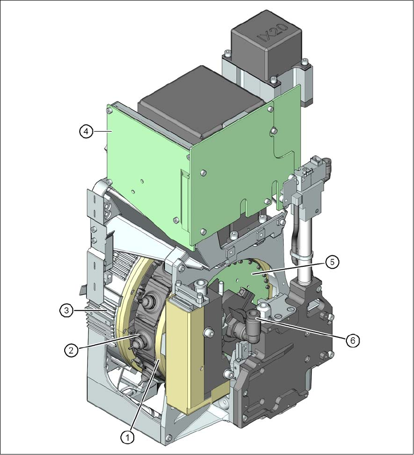
3.5.2 SIPLACE MultiStar
3
Fig. 3.5 - 3 SIPLACE MultiStar - front view, function groups part 1
(1) Star with 12 segments
(2) Segment with integral DP drive
(3) Torque motor for the star drive
(4) Intermediate distributor board
(5) Control board for the 12 DP drives
(6) Compressed air connection for the Venturi nozzles in the pick-up/placement and holding cir-
cuit
Technical data for the machine User manual SIPLACE X-series
Placement head From software version SR.70x.xx 01/2011 EN edition
128
3
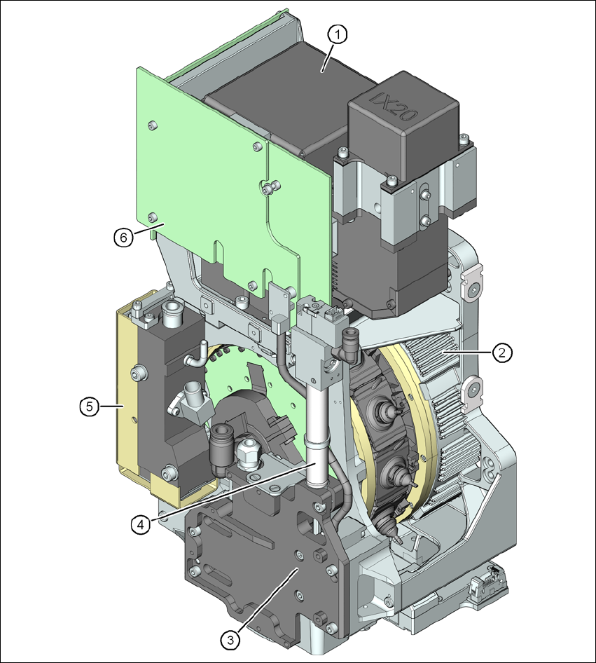
Fig. 3.5 - 4 SIPLACE MultiStar - front view, function groups part 2
(1) C&P component camera, type 30, 27 x 27, digital
(2) Torque motor for the star drive
(3) Z drive (linear motor)
(4) Return cylinder
(5) Pressure control valve
User manual SIPLACE X-series Technical data for the machine
From software version SR.70x.xx 01/2011 EN edition Placement head
129
3
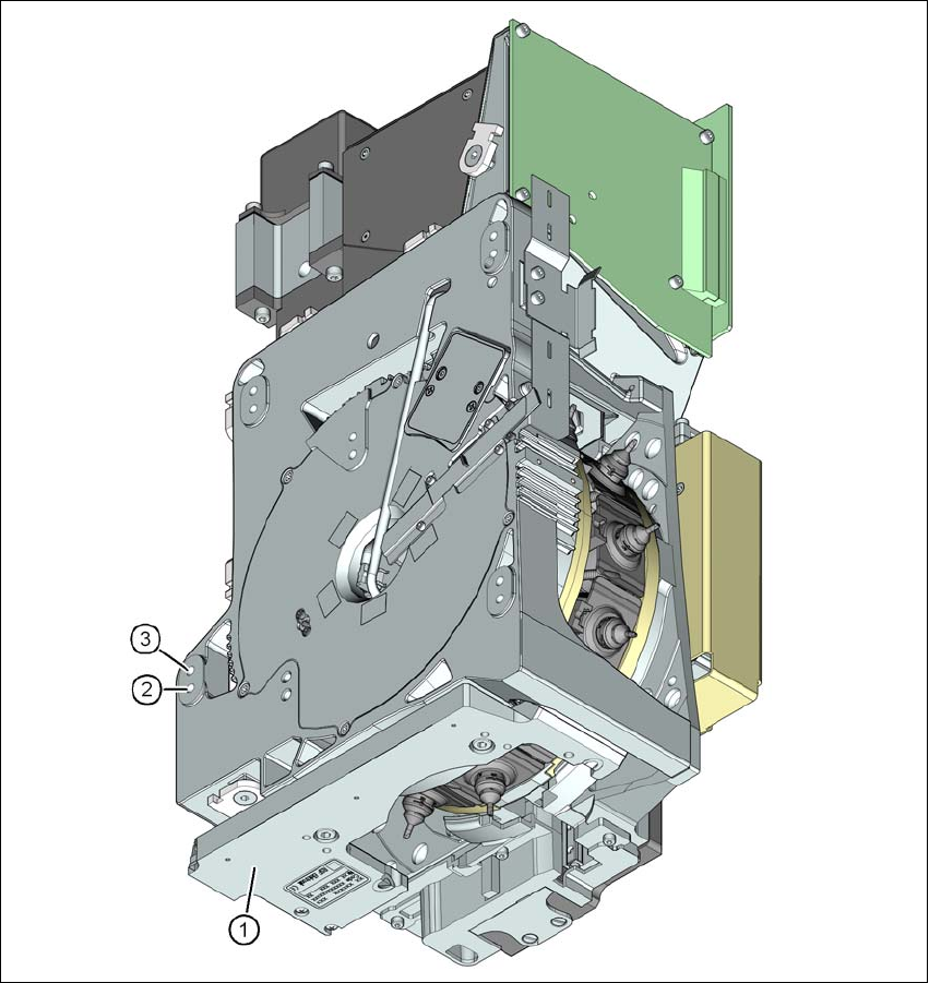
Fig. 3.5 - 5 SIPLACE MultiStar - back view, function groups part 3
(1) Component sensor
(2) Mounting position for component heights up to 11.5 mm
(3) Mounting position for component heights up to 6 mm
3.5.2.1 Description
The MultiStar brings together the two opposing properties of high placement rate and high flexi-
bility. For small components up to 27 x 27 mm², the MultiStar uses the Collect&Place method, i.e.
works with a high placement rate. The components are optically centered with the integrated com-