00196504-02_UM_X-Serie_SR70X_EN.pdf - 第131页
User manual SIPLACE X-series Technical data for the machine From software version SR.70x.x x 01/2011 EN edition Placement head 131 – T winS tar 3.5.2.3 Classification of the componen t range to be processed 3 3.5.2.4 Mul…
Technical data for the machine User manual SIPLACE X-series
Placement head From software version SR.70x.xx 01/2011 EN edition
130
ponent camera. With large component up to 50 x 40 mm², the placement head works on the
Pick&Place principle in which the components are optically centered with the stationary camera.
It was this combination of the two placement procedures (C&P and P&P) that gave the MultiStar
its name. It is abbreviated to CPP head.
The 12 segments of the CPP head are arranged in a star. A high-torque motor turns the star about
the horizontal axis, known as the star axis.
Each segment has a separate DP drive for rotating the nozzle. The nozzles are therefore no lon-
ger rotated into the correct position at a single head station. They can be rotated into their place-
ment position at any time and independently of one another.
Each segment has a separate vacuum generator. This greatly reduces the time taken to switch
between vacuum and forced air. It also allows a vacuum check to be carried out in the holding
circuit for each individual nozzle.
The Z drive for the segments is implemented with a linear motor with linear path measuring sys-
tem, and is thus extremely precise. In the pick-up/placement position, the Z drive moves the seg-
ments up or down in the vertical direction.
As with all SIPLACE Collect&Place heads, the digital component camera is integrated into the
placement head. This omission of additional traversing paths for the optical centering of the com-
ponents contributes to the fast processing speed.
The component sensor on the underside of the placement head measures the components at
the pick-up/placement position. Measurements can be taken at the tip of the nozzle for each
movement of the Z axis, which will give an indication of whether there is a component sticking at
the nozzle and how high the component is.
3.5.2.2 Mounting positions for the SIPLACE MultiStar
The CPP head can be fitted in two different positions on the head mount.
– MultiStar in the upper mounting position
In this position, all components up to 50 x 40 mm² and up to 11.5 mm can be processed. 3
– MultiStar in the lower mounting position
In this position, the CPP head can place components up to 27 x 27 mm² and up to 6 mm high
using the Collect&Place method. 3
Please note the following rules when determining the mounting position:
→ The head height must be the same for all placement heads within a placement area.
→ Always install the CPP head in the upper mounting position if it is combined with the following
modules:
– Stationary component camera
– Matrix tray changer
User manual SIPLACE X-series Technical data for the machine
From software version SR.70x.xx 01/2011 EN edition Placement head
131
– TwinStar
3.5.2.3 Classification of the component range to be processed
3
3.5.2.4 MultiStar placement modes
The CPP head works in different placement modes according to the component class. The set-up
optimization selects the placement mode with the minimum cycle times. The following table illus-
trates the association between the component class and placement mode.
Tab. 3.5 - 2 Relationships between the component class and placement modes
3
3
Component
class
Component
size
Mounting position
a
for the CPP head
Component
height
CO camera type
Small compo-
nent
K_BE
01005
b
-
27 x 27 mm²
upper up to 8.5 mm
Head camera,
type 30
lower up to 6 mm
01005
b
-
16 x 16 mm²
lower up to 6 mm
Head camera,
type 38
Medium-sized
component, type
M_BE_1
< 27 x 27 mm²
upper
between 8.5 and
11.5 mm
Stationary CO
camera,
type 33
(see Section 6.7.1
,
page 406
)
lower not possible
Medium-sized
component, type
M_BE_2
between
27 x 27 mm²
and 32 x 32 mm²
upper 11.5 mm
lower not possible
Large compo-
nent
G_BE
between 32 x
32 mm² and
50 x 40 mm²
upper up to 11.5 mm Stationary CO
camera,
type 33
lower not possible
Tab. 3.5 - 1 Classification of the component range to be processed
a) Please follow the rules for the height of the mounting positions in section 3.5.2.2, page 130.
b) 01005 components: camera type 30; type 38 camera recommended for high quality requirements
Placement mode Component class
Small component Medium-sized
component
Large component
Collect&Place
mode
yes no no
Mixed mode yes yes no
Extended Pick&Place
mode
yes yes yes
Pure
Pick&Place mode
no no yes
Technical data for the machine User manual SIPLACE X-series
Placement head From software version SR.70x.xx 01/2011 EN edition
132
3.5.2.5 MultiStar mounting positions on the machine
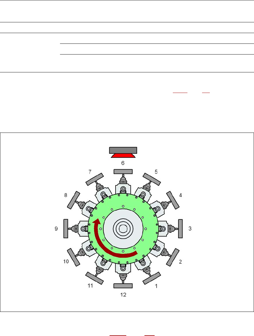
3.5.2.6 MultiStar in Collect&Place mode
In this mode, the MultiStar processes small components.
3
Fig. 3.5 - 6 MultiStar - Collect&Place mode
K_BE Small component (see table 3.5 - 1, page 131)
Type 30/38 Component camera, type 30 or type 38
1 ... 12 Order in which the components are picked up
Placement machine Mounting position
a
CPP head
Maximum component
height
Vision camera
SIPLACE X4I lower only 6 mm Head camera
SIPLACE X4, X3, X2 lower 6 mm Head camera
upper 8.5 mm Head camera
upper only 11.5 mm
Stationary component
camera
Tab. 3.5 - 3 CPP head mounting positions on the machine
a) Please follow the rules for the height of the mounting positions in section 3.5.2.2, page 130.
Type 30/38