00196504-02_UM_X-Serie_SR70X_EN.pdf - 第148页
Technical data for the machine User manual SIPLACE X-series PCB conveyor system From software version SR.70x.xx 01/2011 EN edition 148 3.7 PCB conveyor system The machine is supplied w ith a single PCB co nveyor as stand…

User manual SIPLACE X-series Technical data for the machine
From software version SR.70x.xx 01/2011 EN edition Gantry system
147
The Y axis essentially consists of the following main modules:
– Y-axis linear motor (primary part) (1)
– Permanent magnet (secondary part of the Y-axis linear motor) (2)
– Linear distance measuring system (3)
– Guide system (4)
– Cable and hose carrier (5)
The Y axis is driven by a linear motor. The secondary part of the drive is made up of permanent
magnets and is mounted on the machine frame. The primary part is bolted to the gantry.
3.6.5 Technical data for the Y axis
3
Drive direct, linear motor
Maximum speed 2.5 m/s
Traversing path 839 mm (SIPLACE X4I)
1430 mm (SIPLACE X4, X3, X2)
Distance measuring system metal linear scale
Scale length 1850 mm
Resolution 1 μm
Technical data for the machine User manual SIPLACE X-series
PCB conveyor system From software version SR.70x.xx 01/2011 EN edition
148
3.7 PCB conveyor system
The machine is supplied with a single PCB conveyor as standard. This conveyor variant is partic-
ularly suitable for very wide PCBs. The optional flexible PCB dual conveyor (see section 3.7.2
,
page 150
) and SIPLACE quad lane conveyor (see section 3.7.6, page 157) are available from the
factory.
3.7.1 PCB single conveyor and flexible PCB dual conveyor
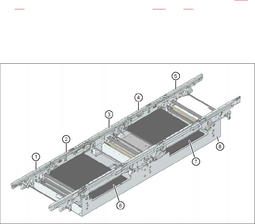
3.7.1.1 Structure of the PCB single conveyor
3
Fig. 3.7 - 1 Structure of the PCB single conveyor
(1) Input conveyor
(2) Processing conveyor 1
(3) Intermediate conveyor
(4) Processing conveyor 2
(5) Output conveyor
(6) Lifting table 1
(7) Lifting table 2
(8) Assembly tray
User manual SIPLACE X-series Technical data for the machine
From software version SR.70x.xx 01/2011 EN edition PCB conveyor system
149
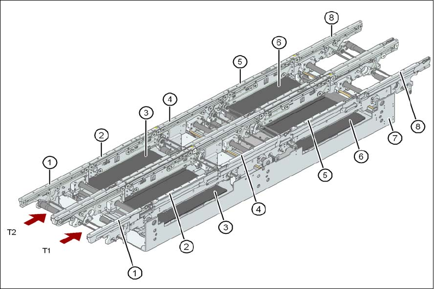
3.7.1.2 Structure of the flexible PCB dual conveyor
The flexible dual conveyor has two conveyor tracks that are electrically and mechanically inde-
pendent of one another.
3
Fig. 3.7 - 2 Structure of the PCB dual conveyor
(1) Input conveyor
(2) Processing conveyor 1
(3) Lifting table 1
(4) Intermediate conveyor
(5) Processing conveyor 2
(6) Lifting table 2
(7) Assembly tray
(8) Output conveyor
T1 Conveyor track 1
T2 Conveyor track 2
3.7.1.3 Description
The PCB conveyors are designed as five-part conveyors with single conveyor, processing con-
veyor 1, intermediate conveyor, processing conveyor 2 and output conveyor. The three areas of