00196504-02_UM_X-Serie_SR70X_EN.pdf - 第149页
User manual SIPLACE X-series Technical data for the machine From software version SR.70x.xx 01/ 2011 EN edition PCB conveyor system 149 3.7.1.2 Structure of the flex ible PCB dual conveyor The flexible dual conveyor has …
Technical data for the machine User manual SIPLACE X-series
PCB conveyor system From software version SR.70x.xx 01/2011 EN edition
148
3.7 PCB conveyor system
The machine is supplied with a single PCB conveyor as standard. This conveyor variant is partic-
ularly suitable for very wide PCBs. The optional flexible PCB dual conveyor (see section 3.7.2
,
page 150
) and SIPLACE quad lane conveyor (see section 3.7.6, page 157) are available from the
factory.
3.7.1 PCB single conveyor and flexible PCB dual conveyor
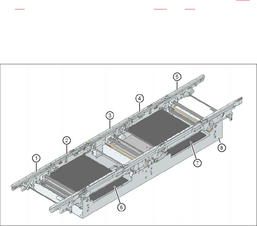
3.7.1.1 Structure of the PCB single conveyor
3
Fig. 3.7 - 1 Structure of the PCB single conveyor
(1) Input conveyor
(2) Processing conveyor 1
(3) Intermediate conveyor
(4) Processing conveyor 2
(5) Output conveyor
(6) Lifting table 1
(7) Lifting table 2
(8) Assembly tray
User manual SIPLACE X-series Technical data for the machine
From software version SR.70x.xx 01/2011 EN edition PCB conveyor system
149
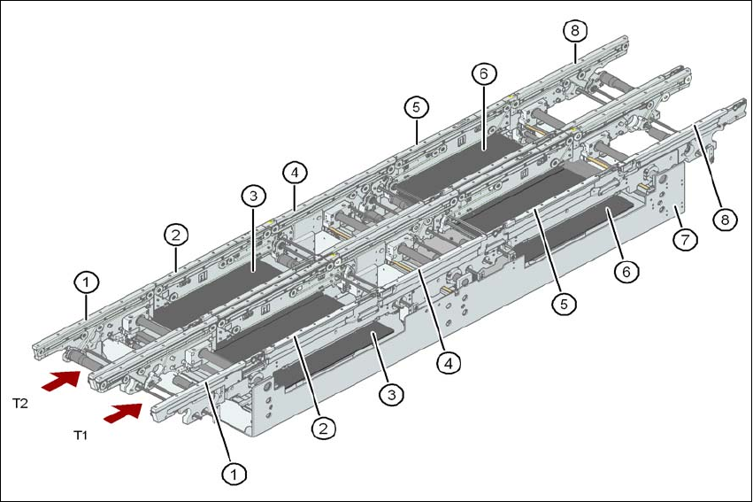
3.7.1.2 Structure of the flexible PCB dual conveyor
The flexible dual conveyor has two conveyor tracks that are electrically and mechanically inde-
pendent of one another.
3
Fig. 3.7 - 2 Structure of the PCB dual conveyor
(1) Input conveyor
(2) Processing conveyor 1
(3) Lifting table 1
(4) Intermediate conveyor
(5) Processing conveyor 2
(6) Lifting table 2
(7) Assembly tray
(8) Output conveyor
T1 Conveyor track 1
T2 Conveyor track 2
3.7.1.3 Description
The PCB conveyors are designed as five-part conveyors with single conveyor, processing con-
veyor 1, intermediate conveyor, processing conveyor 2 and output conveyor. The three areas of

Technical data for the machine User manual SIPLACE X-series
PCB conveyor system From software version SR.70x.xx 01/2011 EN edition
150
input conveyor, intermediate conveyor and output conveyor act as buffer zones for the PCBs if
shorter waiting times are required.
The conveyor belts are driven by DC motors. Optical sensors monitor and control the movement
of the board. If the board has reached placement area and passed the light barrier, it is braked. A
laser light barrier determines the position of the board. As soon as the circuit board has reached
its target position, the conveyor belt is stopped and the board is clamped from below.
The distance between the top of the PCB and the placement head thus remains unchanged for
each PCB, and is not dependent on the thickness of the PCB. The placement rate is thus inde-
pendent of the PCB thickness. The PCB fiducial centering can also be optimized. Since the dis-
tance between the PCB surface and the PCB camera remains the same, the PCB camera is
always focused on the PCB surface with the same sharpness. The PCB fiducial contours are op-
timally mapped on the CCD chip of the PCB camera.
The width of the circuit board conveyor is set and monitored by an integral control circuit. It can
be selected by calling up the program. The control circuit then actuates the stepping motors until
the desired width is reached. The width adjustment is therefore independent of other machine
components.
The conveyor height can be modified on the machine, thus allowing it to be integrated into lines
with a transport height of 830, 900, 930 or 950 mm. The standard height is 930 mm.
The PCB conveyors communicate with the individual machines via the SMEMA interface or the
optional Siemens interface.
The fixed transport side can be located on the left or right for both the dual conveyor and the single
conveyor. With this conveyor, the fixed side can be easily switched from right to left and vice versa
using the station software.
3.7.2 Flexible PCB dual conveyor - transport lanes and transport modes
The right conveyor lane (viewed in the transport direction) is designated "Conveyor 1" and the left
as "Conveyor 2" (see Fig. 3.7 - 4
, page 152).
3.7.2.1 PCB dual conveyor in Single conveyor mode
The dual conveyor can be configured online to create a single conveyor. To do this, one conveyor
track is moved fully together and deactivated (see Fig. 3.7 - 3
). This gives a conveyor track width
of up to 450 mm.