00196504-02_UM_X-Serie_SR70X_EN.pdf - 第151页
User manual SIPLACE X-series Technical data for the machine From software version SR.70x.xx 01/ 2011 EN edition PCB conveyor system 151 3 Fig. 3.7 - 3 Flexible dual conv eyor in Single conveyor mode 3.7.2.2 Asynchronous …

Technical data for the machine User manual SIPLACE X-series
PCB conveyor system From software version SR.70x.xx 01/2011 EN edition
150
input conveyor, intermediate conveyor and output conveyor act as buffer zones for the PCBs if
shorter waiting times are required.
The conveyor belts are driven by DC motors. Optical sensors monitor and control the movement
of the board. If the board has reached placement area and passed the light barrier, it is braked. A
laser light barrier determines the position of the board. As soon as the circuit board has reached
its target position, the conveyor belt is stopped and the board is clamped from below.
The distance between the top of the PCB and the placement head thus remains unchanged for
each PCB, and is not dependent on the thickness of the PCB. The placement rate is thus inde-
pendent of the PCB thickness. The PCB fiducial centering can also be optimized. Since the dis-
tance between the PCB surface and the PCB camera remains the same, the PCB camera is
always focused on the PCB surface with the same sharpness. The PCB fiducial contours are op-
timally mapped on the CCD chip of the PCB camera.
The width of the circuit board conveyor is set and monitored by an integral control circuit. It can
be selected by calling up the program. The control circuit then actuates the stepping motors until
the desired width is reached. The width adjustment is therefore independent of other machine
components.
The conveyor height can be modified on the machine, thus allowing it to be integrated into lines
with a transport height of 830, 900, 930 or 950 mm. The standard height is 930 mm.
The PCB conveyors communicate with the individual machines via the SMEMA interface or the
optional Siemens interface.
The fixed transport side can be located on the left or right for both the dual conveyor and the single
conveyor. With this conveyor, the fixed side can be easily switched from right to left and vice versa
using the station software.
3.7.2 Flexible PCB dual conveyor - transport lanes and transport modes
The right conveyor lane (viewed in the transport direction) is designated "Conveyor 1" and the left
as "Conveyor 2" (see Fig. 3.7 - 4
, page 152).
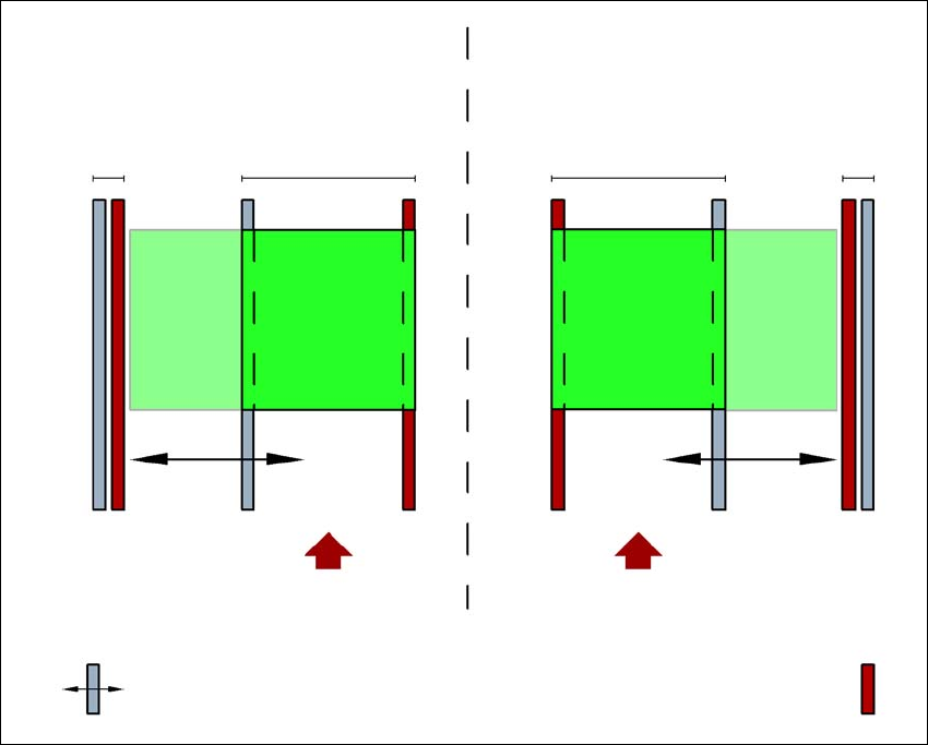
3.7.2.1 PCB dual conveyor in Single conveyor mode
The dual conveyor can be configured online to create a single conveyor. To do this, one conveyor
track is moved fully together and deactivated (see Fig. 3.7 - 3
). This gives a conveyor track width
of up to 450 mm.
User manual SIPLACE X-series Technical data for the machine
From software version SR.70x.xx 01/2011 EN edition PCB conveyor system
151
3
Fig. 3.7 - 3 Flexible dual conveyor in Single conveyor mode
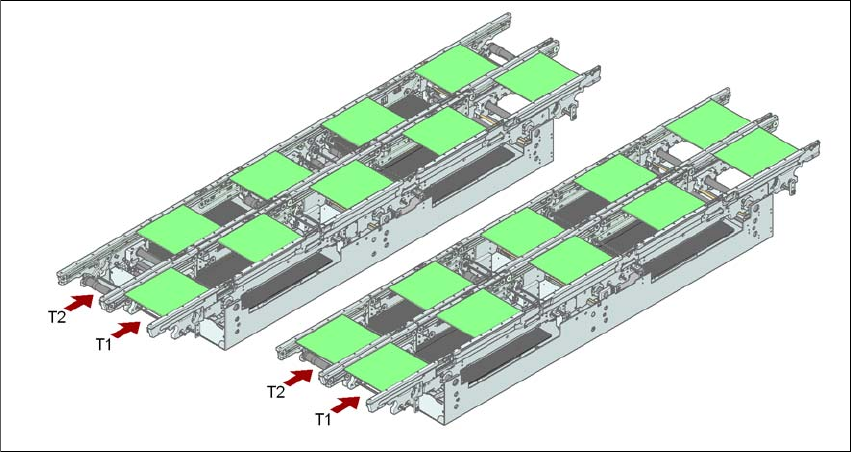
3.7.2.2 Asynchronous transport mode
In asynchronous mode, only one PCB in a transport track is processed. At the same time, another
PCB in the second transport track is moved into the placement position. This saves the full con-
veying time of one PCB, thus considerably increasing performance, particularly for PCBs with a
short cycle time.
Once the machine has received the job data (panel, set-up), the PCBs on the feeding belts are
continuously transported to the available processing belt (provided that the processing belt is free)
throughout the placement operation. The placement sequence starts as soon as a PCB has
moved onto the processing belt. The PCBs are processed one after another.
If the placement sequence is interrupted, the conveyor interface will be disabled and the PCBs
currently on the processing belts will be completed.
The conveyor interface is disabled or enabled simultaneously for both transport tracks.
Dual conveyor with widened conveyor track 2
(stationary conveyor side wall on left)
Conveyor track 2
deactivated
Conveyor track 1 Conveyor track 2 Conveyor track 1
deactivated
PCB transport direction PCB transport direction
Stationary conveyor side wall
Dual conveyor with widened conveyor track 1
(stationary conveyor side wall on right)
Movable conveyor side wall
Technical data for the machine User manual SIPLACE X-series
PCB conveyor system From software version SR.70x.xx 01/2011 EN edition
152
3
Fig. 3.7 - 4 Transport modes
3.7.2.3 Synchronous transport mode
In synchronous mode, two PCBs of the same size are moved into the placement position at the
same time. They must be processed as a common panel.
This allows both the top and the underside of a PCB to be processed on the same line. The time
taken to move the PCBs is reduced as there are always two PCBs being transported at the same
time. It also ensures better utilization of the nozzle configuration.
PCBs on conveyor tracks 1 and 2 are moved synchronously onto the conveyor sections (i.e. the
conveyors are controlled synchronously, but independently of one another). The components to
be placed on conveyor tracks 1 and 2 must be organized into a panel via two subpanels. (See the
SIPLACE Pro user manual).
If only one conveyor track is full when the placement sequence starts, the subpanel on this section
will be identified as "not for placement".
If the dual conveyor is operated in synchronous mode, the ‘PCB whispering down the line’ option
is deactivated. The "Global bad fiducial" option cannot be used.
3.7.2.4 I-placement (SIPLACE X4I only)
Another placement concept has now been developed for the SIPLACE X4I in addition to synchro-
nous and asynchronous transport modes. This is known as I-placement. In this mode, the two
placement heads work simultaneously in one placement area and populate a PCB totally indepen-
dently of one another. Normally the placement heads work in alternating placement mode: while
the placement head is placing a PCB in one placement area, the other placement head picks up
Synchronous transport modeAsynchronous transport mode