00196504-02_UM_X-Serie_SR70X_EN.pdf - 第153页
User manual SIPLACE X-series Technical data for the machine From software version SR.70x.xx 01/ 2011 EN edition PCB conveyor system 153 components fro m the feeder modules. With "I-placement", there ar e no suc…
Technical data for the machine User manual SIPLACE X-series
PCB conveyor system From software version SR.70x.xx 01/2011 EN edition
152
3
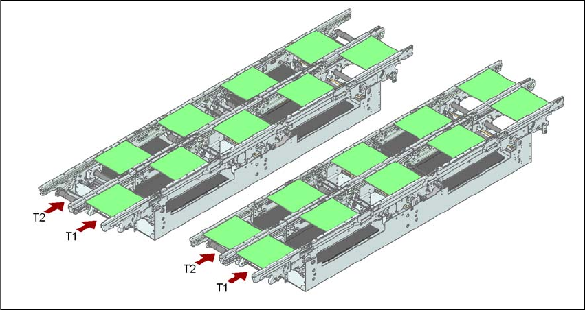
Fig. 3.7 - 4 Transport modes
3.7.2.3 Synchronous transport mode
In synchronous mode, two PCBs of the same size are moved into the placement position at the
same time. They must be processed as a common panel.
This allows both the top and the underside of a PCB to be processed on the same line. The time
taken to move the PCBs is reduced as there are always two PCBs being transported at the same
time. It also ensures better utilization of the nozzle configuration.
PCBs on conveyor tracks 1 and 2 are moved synchronously onto the conveyor sections (i.e. the
conveyors are controlled synchronously, but independently of one another). The components to
be placed on conveyor tracks 1 and 2 must be organized into a panel via two subpanels. (See the
SIPLACE Pro user manual).
If only one conveyor track is full when the placement sequence starts, the subpanel on this section
will be identified as "not for placement".
If the dual conveyor is operated in synchronous mode, the ‘PCB whispering down the line’ option
is deactivated. The "Global bad fiducial" option cannot be used.
3.7.2.4 I-placement (SIPLACE X4I only)
Another placement concept has now been developed for the SIPLACE X4I in addition to synchro-
nous and asynchronous transport modes. This is known as I-placement. In this mode, the two
placement heads work simultaneously in one placement area and populate a PCB totally indepen-
dently of one another. Normally the placement heads work in alternating placement mode: while
the placement head is placing a PCB in one placement area, the other placement head picks up
Synchronous transport modeAsynchronous transport mode

User manual SIPLACE X-series Technical data for the machine
From software version SR.70x.xx 01/2011 EN edition PCB conveyor system
153
components from the feeder modules. With "I-placement", there are no such waiting times for the
placement heads, which increases the placement rate.
3.7.3 Controlling and width adjustment
3.7.3.1 Controlling using the Single Functions menu
The online help contains information on controlling the PCB conveyor system and on the Single
Functions menu.
3.7.3.2 Automatic width adjustment
When the command is received, the conveyor belts are set to the desired width. Different widths
are possible for a dual conveyor.
*See the Online Help for detailed information about changing the conveyor track width.
3.7.4 Technical data
3.7.4.1 Technical data for the PCB single conveyor - SIPLACE X4I
3
Fixed conveyor side right or left
PCB formats (length x width)
Standard 50 x 50 mm² to 380 x 535 mm²
a
PCB thickness (Standard) 0.3 mm to 4.5 mm (thicker PCBs available on
request)
PCB warpage see Section 3.7.8
, page 159
PCB weight max. 3 kg
Clearance on PCB underside (standard) 25 mm ± 0.2 mm
Component-free PCB handling edge min. 3.1 mm
PCB changeover time < 2.5 s
PCB positioning accuracy ± 0.5 mm
PCB conveyor height 830 mm ± 15 mm (optional)
900 mm ± 15 mm (optional)
930 mm ± 15 mm (standard)
950 mm ± 15 mm (SMEMA: optional)
Type of interface SMEMA / Siemens
b
Bad fiducial detection standard
Automatic width adjustment standard
a) With PCB widths > 450 mm make sure that the peripheral modules are also able to process these widths.
b) Option.

Technical data for the machine User manual SIPLACE X-series
PCB conveyor system From software version SR.70x.xx 01/2011 EN edition
154
3.7.4.2 Technical data for the flexible PCB dual conveyor - SIPLACE X4I
3
3.7.4.3 Technical data for the PCB single conveyor - SIPLACE X4, X3, X2
3
Fixed conveyor side right or left or both outer conveyor sides
stationary
PCB formats (length x width)
Flexible dual conveyor
standard 50 x 50 mm² to 380 x 250 mm²
Dual conveyor in "Single conveyor mode"
standard 50 x 50 mm² to 380 x 436.5 mm²
PCB thickness (Standard) 0.3 mm to 4.5 mm (thicker PCBs available on
request)
PCB warpage see Section 3.7.8
, page 159
PCB weight max. 3 kg
Clearance on PCB underside (standard) 25 mm ± 0.2 mm
PCB conveyor height 830 mm ± 15 mm (optional)
900 mm ± 15 mm (optional)
930 mm ± 15 mm (standard)
950 mm ± 15 mm (SMEMA: optional)
Type of interface SMEMA / Siemens
a
a) Option.
Component-free PCB handling edge min. 3.1 mm
PCB changeover time < 2.5 s
PCB positioning accuracy ± 0.5 mm
Conveyor mode I-placement, synchronous or asynchronous
(selected via the software)
Components for each type of conveyor Same or different
PCB width for each type of conveyor Same or different
Bad fiducial detection synchronous: standard, no global ink spot
asynchronous: standard
Automatic width adjustment synchronous: standard
asynchronous: standard
Fixed conveyor side right or left
PCB formats (length x width)
Standard 50 x 50 mm² to 450 x 535 mm²
a
PCB thickness (Standard) 0.3 mm to 4.5 mm
(thicker PCBs available on request)