00196504-02_UM_X-Serie_SR70X_EN.pdf - 第164页
Technical data for the machine User manual SIPLACE X-series Vision system From software vers ion SR .70x.xx 01/2011 EN edition 164 3.8.2.3 IC and FC cameras on the X2 machine 3 Fig. 3.8 - 3 IC and FC cameras on the X2 ma…
User manual SIPLACE X-series Technical data for the machine
From software version SR.70x.xx 01/2011 EN edition Vision system
163
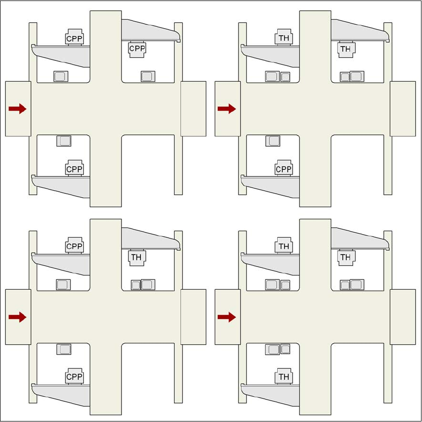
3.8.2.2 IC and FC cameras on the X3 machine
3
Fig. 3.8 - 2 IC and FC cameras on the X3 machine
CPP MultiStar
TH TwinStar
25 FC camera, type 25
33 IC camera, type 33
G1, G3, G4 Gantry 1, gantry 3, gantry 4
33
25 and 33
33 33 and 25 25 and 33
33
G3 G3
G4
G4
G1
G1
G4
G3
G1
33
33
33
33 and 25 25 and 33
G3
G4
G1
33 and 25
Technical data for the machine User manual SIPLACE X-series
Vision system From software version SR.70x.xx 01/2011 EN edition
164
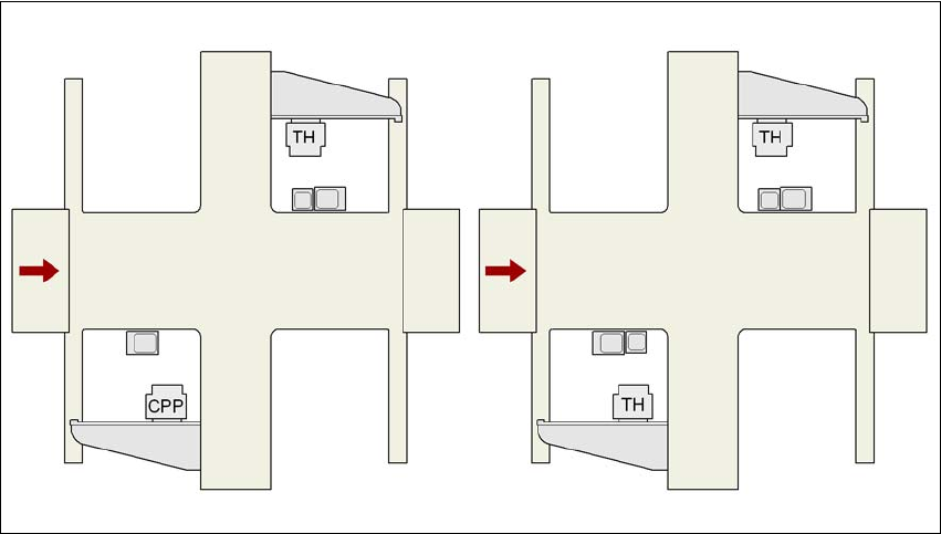
3.8.2.3 IC and FC cameras on the X2 machine
3
Fig. 3.8 - 3 IC and FC cameras on the X2 machine
CPP MultiStar
TH TwinStar
25 FC camera, type 25
33 IC camera, type 33
G1, G3 Gantry 1, gantry 3
25 and 33
33 and 25
25 and 33
G3 G3
G1
G1
33
User manual SIPLACE X-series Technical data for the machine
From software version SR.70x.xx 01/2011 EN edition Vision system
165
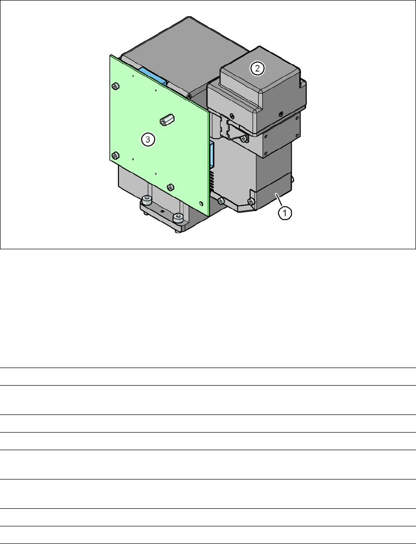
3.8.3 C&P component camera, type 30, 27 x 27, digital
3.8.3.1 Structure
3
Fig. 3.8 - 4 C&P component camera, type 30, 27 x 27, digital
(1) Component camera lens and illumination
(2) Camera amplifier
(3) Illumination control
3.8.3.2 Technical data
3
Component dimensions 0.3 x 0.3 mm² to 27 x 27 mm²
Range of components 01005to 27 x 27 mm²
PLCC, SO, QFP, TSDP, SOT, MELF, CHIP, IC BGA
Min. lead pitch 0.3 mm
Min. lead width 0.15 mm
Min. ball pitch 0.25 mm for components < 18 x 18 mm²
0.35 mm for components 18 x 18 mm²
Min. ball diameter 0.14 mm for components < 18 x 18 mm²
0.2 mm for components 18 x 18 mm²
Field of vision 32 x 32 mm²
Method of illumination Front-illumination (5 levels, programmable as required)