00196504-02_UM_X-Serie_SR70X_EN.pdf - 第185页
User manual SIPLACE X-series Technical data for the machine From software version SR.70x.xx 01/2011 EN edition X feeder modules 185 component is wetted and then the flux laye r is renewed. This sequence guarante es consi…
Technical data for the machine User manual SIPLACE X-series
X feeder modules From software version SR.70x.xx 01/2011 EN edition
184
3.9.3 X linear dipping unit (LDU X)
Item no. 00117011-xx Linear dip module for flux / LDU-X
Item no. dip plates see Section 3.9.3.5
, page 186
3
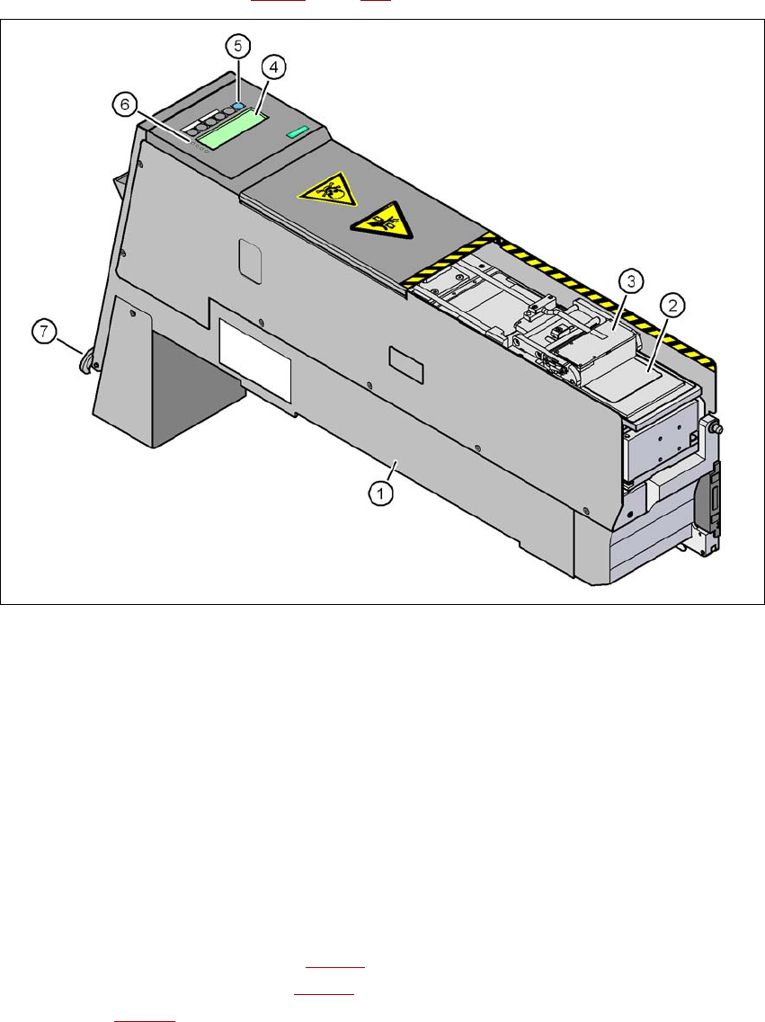
Fig. 3.9 - 13 Linear Dipping Unit (LDU X)
(1) LDU X
(2) Dip plate
(3) Flux container
(4) Display panel (4 lines each with 20 characters)
(5) Operator panel with 6 membrane keys
(6) LED for status displays
(7) EMERGENCY OFF button
3.9.3.1 Description
The X linear dipping unit (item 1 in Fig. 3.9 - 13) is used to wet flip-chip and CSP components with
flux. The flux container item 3 in Fig. 3.9 - 13
) slides with a linear movement over the dip plate
(item 2 in Fig. 3.9 - 13
) and applies the flux at a defined layer thickness in the depression in the
dip plate. The parameters for wetting a component with flux are prescribed in SIPLACE Pro. The

User manual SIPLACE X-series Technical data for the machine
From software version SR.70x.xx 01/2011 EN edition X feeder modules
185
component is wetted and then the flux layer is renewed. This sequence guarantees consistent
processing conditions for the components.
The individual menus for actions and operating parameters are displayed in the display panel
(item 4 in Fig. 3.9 - 13
, page 184). The menus can be selected or a parameter modified and stored
using the buttons on the operator panel (item 5 in Fig. 3.9 - 13
, page 184). The 4 LEDs (item 6 in
Fig. 3.9 - 13
, page 184) of the display panel signalizes the status of the LDU-X. The LDU-X is
switched off immediately when the emergency stop button is pressed (item 7 in Fig. 3.9 - 13
, page
184
).
The LDU-X is suitable for both the MultiStar and the TwinStar. It is added to the set-up as a stand-
alone feeder module type. The module can only be set up on a component trolley of the SIPLACE
X-series. An implemented warming function allows the viscosity of the flux to be altered. The LDU-
X can be operated outside the machines using the energy and data interface for X feeder modules
(see Section 3.9.5
, page 191) for test purposes.
3.9.3.2 Technical data
Further technical data and details can be found in the "SIPLACE LDU-X" user manual.
May be installed on the following machines SIPLACE X4I, X4, X3, X2
Filled 8mm locations on the CO trolley of the
SIPLACE X-series
9
Component size a max. of 55 x 55 mm², depending on the
placement head type;
a max. of 45 x 45 mm² for TwinStar
The adjustable flux layer thickness 15 - 260 μm
Tolerance of the layer thicknesses ± 5 μm ... ± 10 µm
Time for applying the flux to the dip plate > 3s
Component dipping time adjustable using the software
Flux Indium TACFlux 010 / 013
Kester TSF-6502 / 6522
Alphametals OM338 / OM338PT
Almit BM1 RMA
Cookson WS 3018lv
et al.
Possible placement heads MultiStar, SpeedStar, TwinStar

Technical data for the machine User manual SIPLACE X-series
X feeder modules From software version SR.70x.xx 01/2011 EN edition
186
3.9.3.3 Options for combining the LDU-X with placement heads
3
3.9.3.4 Restrictions
– Limited pick-up area for the placement heads:
SIPLACE X4I: at all locations
SIPLACE X4/X3/X2: at locations 1 and 3
– The LDU-X must be manually added to the set-up.
– The LDU-X must only be set up on lanes 7 - 26.
– Only one LDU-X may be added to each component trolley.
– The waffle-pack tray holder and the LDU-X must not be set up on one component trolley.
– Linear feeders must not be set up beside an LDU-X.
– MTC and LDU-X must only be set up in a PA with a gantry.
– A gantry can only pick up from one LDU-X, even if it can pick up from two locations.
3.9.3.5 Dip plates for specified flux layer thicknesses
PLEASE NOTE 3
Please note that the flux thickness depends on the flux that is used. Even if the component and
the desired flux height are the same, the required dip plate depth can vary with different fluxes.
Placement heads
Machine C&P20 CPP (upper
mounting position)
CPP (lower
mounting position)
TH
SIPLACE X4I Yes
a
a) With LDU-X only from function status 02
Not applicable Yes Not applicable
SIPLACE X4 Yes
a
Yes Yes Yes
SIPLACE X3 Yes
a
Yes Yes Yes
SIPLACE X2 Yes
a
Yes Yes Yes
Dip plate depth Item no.
20 μm 00117022-xx
25 μm 00117020-xx
30 μm 00117023-xx
45 μm 00117043-xx