00196504-02_UM_X-Serie_SR70X_EN.pdf - 第187页
User manual SIPLACE X-series Technical data for the machine From software version SR.70x.xx 01/2011 EN edition X feeder modules 187 60 μ m 0011702 6-xx 70 μ m 0011702 7-xx 75 μ m 0011702 1-xx 80 μ m 0011702 8-xx 90 μ m 0…

Technical data for the machine User manual SIPLACE X-series
X feeder modules From software version SR.70x.xx 01/2011 EN edition
186
3.9.3.3 Options for combining the LDU-X with placement heads
3
3.9.3.4 Restrictions
– Limited pick-up area for the placement heads:
SIPLACE X4I: at all locations
SIPLACE X4/X3/X2: at locations 1 and 3
– The LDU-X must be manually added to the set-up.
– The LDU-X must only be set up on lanes 7 - 26.
– Only one LDU-X may be added to each component trolley.
– The waffle-pack tray holder and the LDU-X must not be set up on one component trolley.
– Linear feeders must not be set up beside an LDU-X.
– MTC and LDU-X must only be set up in a PA with a gantry.
– A gantry can only pick up from one LDU-X, even if it can pick up from two locations.
3.9.3.5 Dip plates for specified flux layer thicknesses
PLEASE NOTE 3
Please note that the flux thickness depends on the flux that is used. Even if the component and
the desired flux height are the same, the required dip plate depth can vary with different fluxes.
Placement heads
Machine C&P20 CPP (upper
mounting position)
CPP (lower
mounting position)
TH
SIPLACE X4I Yes
a
a) With LDU-X only from function status 02
Not applicable Yes Not applicable
SIPLACE X4 Yes
a
Yes Yes Yes
SIPLACE X3 Yes
a
Yes Yes Yes
SIPLACE X2 Yes
a
Yes Yes Yes
Dip plate depth Item no.
20 μm 00117022-xx
25 μm 00117020-xx
30 μm 00117023-xx
45 μm 00117043-xx

User manual SIPLACE X-series Technical data for the machine
From software version SR.70x.xx 01/2011 EN edition X feeder modules
187
60 μm 00117026-xx
70 μm 00117027-xx
75 μm 00117021-xx
80 μm 00117028-xx
90 μm 00117029-xx
100 μm 00117030-xx
110 μm 00117038-xx
120 μm 00117031-xx
130 μm 00117039-xx
140 μm 00117044-xx
150 μm 00117045-xx
160 μm 00117046-xx
170 μm 00117054-xx
180 μm 00117047-xx
190 μm 00117048-xx
200 μm 00117049-xx
210 μm 00117042-xx
220 μm 00117032-xx
230 μm 00117033-xx
240 μm 00117037-xx
250 μm 00117051-xx
260 μm 00117052-xx
270 μm 00117053-xx
280 μm 00117034-xx
290 μm 00117055-xx
300 μm 00117041-xx
310 μm 00117056-xx
320 μm 00117035-xx
330 μm 00117057-xx
340 μm 00117058-xx
350 μm 00117059-xx
360 μm 00117036-xx
370 μm 00117061-xx
380
μm 00117062-xx
390 μm 00117063-xx
400 μm 00117040-xx
Technical data for the machine User manual SIPLACE X-series
X feeder modules From software version SR.70x.xx 01/2011 EN edition
188
3.9.4 Feeder module adapter for the X-series
Item no. 00141305-xx Adapter for the X-series feeder modules
Item no. 00141308-xx Adapter plate for Reject Conveyor
Item no. 00141310-xx Adapter plate for SIPLACE label presenter module
3
The spectrum of X tape feeder modules has been extended to include linear vibratory feeders,
label presenter modules and reject conveyors (disposal module). An adapter allows S linear vi-
bratory feeders, label presenter modules and reject conveyors to be set up for use on X-series CO
trolleys. The adapter performs electronic as well as mechanical functions: it converts the commu-
nication signals from the S feeder into signals conforming to the extended X-series protocol. Ad-
ditional functions, such as feeder module identification, have also been implemented.
PLEASE NOTE 3
S linear vibratory feeders, label presenters and reject conveyors cannot be set up on component
trolleys if they have a SpeedStar (C&P20) in the access range.
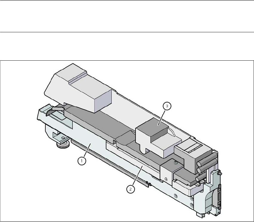
3.9.4.1 Feeder module adapter for the X-series with label presenter module
3
Fig. 3.9 - 14 Feeder module adapter for the X-series with label presenter module
(1) Adapter for the X-series feeder modules (item no. 00141305-xx)
(2) Adapter plate for SIPLACE label presenter module (item no. 00141310-xx)
(3) Label presenter module