00196504-02_UM_X-Serie_SR70X_EN.pdf - 第190页
Technical data for the machine User manual SIPLACE X-series X feeder modules From software version SR.70x.xx 01/2011 EN edition 190 Feeder module locations filled 3 3 S tock of components Up to 150 per steel stick magazi…
User manual SIPLACE X-series Technical data for the machine
From software version SR.70x.xx 01/2011 EN edition X feeder modules
189
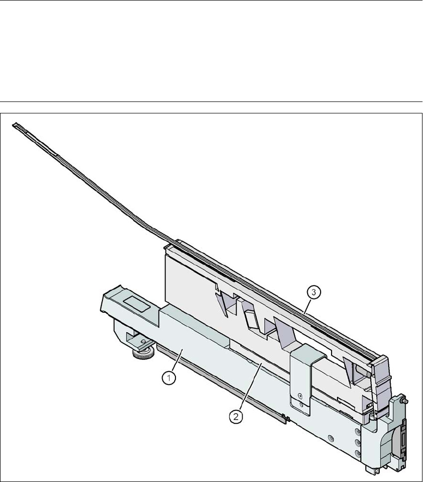
3.9.4.2 Feeder module adapter for the X-series with linear vibratory feeder
PLEASE NOTE 3
An adapter plate is supplied as standard with the adapter for X-series feeder modules:
– The adapter plate should be used for component heights up to 16.5 mm.
– Component heights between 16.5 mm and 25 mm are processed without an adapter
plate.
3
Fig. 3.9 - 15 Feeder module adapter for the X-series with linear vibratory feeder
(1) Adapter for the X-series feeder modules (item no. 00141305-xx)
(2) Adapter plate 16.5 mm (in the deliverables)
(3) Linear vibratory feeder, type 3 (item no. 00142031-xx)
Width 34.4 mm
Tracks per feeder 1, 2 or 3 3
Technical data for the machine User manual SIPLACE X-series
X feeder modules From software version SR.70x.xx 01/2011 EN edition
190
Feeder module locations filled 3 3
Stock of components Up to 150 per steel stick magazine, 3
depending on the component length 3
Specific data for stick magazines 9.5 mm wide / x 3 3
15 mm wide / x 2 3
> 15 mm wide / x 1 3
30 mm wide / 1 x 3
Vibrating time Variable with SIPLACE Pro from 400 to
over 1,000 ms 3
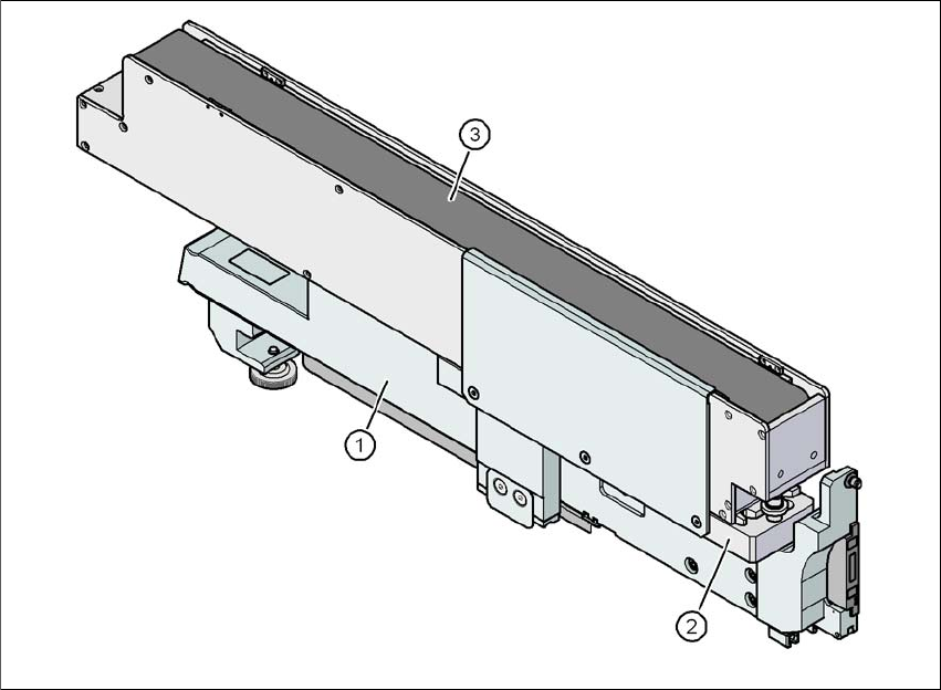
3.9.4.3 Feeder module adapter for the X-series with reject conveyor
3
Fig. 3.9 - 16 Feeder module adapter for the X-series with reject conveyor
(1) Adapter for the X-series feeder modules (item no. 00141305-xx)
(2) Adapter plate for Reject Conveyor (item no. 00141308-xx)
(3) Reject conveyor
User manual SIPLACE X-series Technical data for the machine
From software version SR.70x.xx 01/2011 EN edition X feeder modules
191
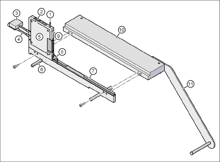
3.9.5 Energy and data interface for X feeder modules
Item no. 00141247-xx Energy and data interface for X feeder module
3
Fig. 3.9 - 17 Energy and data interface for X feeder modules
(1) Button for releasing the locking latch
(2) Operator panel
(3) Data cable
(4) Power supply cable
(5) Electronic housing
(6) Fold-out feet
(7) Omega profile for guiding the feeder modules
(8) Locking latch
(9) Locating hole for the front centering pin of the feeder module
(10) Base plate
(11) Coil holder