00196504-02_UM_X-Serie_SR70X_EN.pdf - 第193页
User manual SIPLACE X-series Technical data for the machine From software version SR.70x.xx 01/2011 EN edition X feeder modules 193 3.9.6 W affle-p ack tray holder for the component trolley from the SIPLACE X-series Item…

Technical data for the machine User manual SIPLACE X-series
X feeder modules From software version SR.70x.xx 01/2011 EN edition
192
3.9.5.1 Description
The energy and data interface allows X feeder modules to be used outside the machine and set-
up area. The interface consists of an aluminum frame with omega profile (item 7 in Fig. 3.9 - 15
,
page 189
) for holding and guiding the feeder modules. The feeder module is placed on the omega
profile with the slider guides, just like the X component trolley, and is pushed forward until the front
centering pin of the feeder module is fully engaged in the locating hole (item 9 in Fig. 3.9 - 15
,
page 189
). The locking latch (item 8 in Fig. 3.9 - 15, page 189) locks the feeder module in this
position. To remove the feeder module, simply press the release button (item 1 in Fig.
3.9 - 15
, page 189). The locking latch (item 8 in Fig. 3.9 - 15, page 189) is pressed down and re-
leases the feeder module. Fold-out feet (item 6 in Fig. 3.9 - 15
, page 189) stabilize the position of
the energy and data interface, particularly for wide feeder modules.
The electronic housing (item 5 in Fig. 3.9 - 15
, page 189) holds the electronic control unit for the
energy and data interface. The operator panel (item 2 in Fig. 3.9 - 15
, page 189) consists of start
and stop buttons and two status LEDs. Communication with a PC takes place via the data cable
(item 3 in Fig. 3.9 - 15
, page 189). The power supply cable (item 4 in Fig. 3.9 - 15, page 189) is
connected to the power supply unit provided.
3.9.5.2 Usage
The energy and data interface is used to check, maintain and repair X feeder modules. It can also
be used for setting up in advance for PCB production. In this case, the energy and data interface
is fixed to the base plate (item 10 in Fig. 3.9 - 19
, page 195). The coil holder (item 11 in Fig. 3.9 -
19, page 195) is also mounted on the base plate. When a component tape is inserted, you can
check or reset the increment, pick-up position and conveyor speed. The detailed user manual de-
scribes how to use the interface and the necessary servicing work.
3.9.5.3 Deliverables
– Single Slot EDIF
a
– Power supply, 100 - 120 / 200 - 240 VAC, +30VDC, 4.3 A
– Base plate with coil arm
– User manual
a) EDIF = energy and data interface
User manual SIPLACE X-series Technical data for the machine
From software version SR.70x.xx 01/2011 EN edition X feeder modules
193
3.9.6 Waffle-pack tray holder for the component trolley from the SIPLACE X-series
Item no. 00141285-xx Waffle-pack tray holder, X-series
3
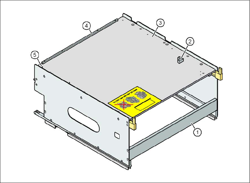
Fig. 3.9 - 18 Waffle-pack tray holder
(1) Waffle-pack tray holder from the SIPLACE X-series
(2) Retaining bracket for a second JEDEC waffle-pack tray
(3) Waffle-pack tray carrier
(4) Stop bars for the JEDEC waffle-pack tray
(5) Dowel pin - Zero point for the JEDEC waffle-pack tray
3
Individually fitted JEDEC waffle-pack trays or waffle-pack magazines can be fixed to the waffle-
pack tray carrier using magnets. If two JEDEC waffle-pack trays are fitted, you must fix them with
locking and retaining rails, as used for the waffle-pack tray carrier on the MTC.
Parts: Item no.:
Magnet 00316593-xx
Locking and retaining rail for JEDEC trays 00372615-xx
Technical data for the machine User manual SIPLACE X-series
X feeder modules From software version SR.70x.xx 01/2011 EN edition
194
3.9.6.1 Technical data
3
3.9.6.2 Number of waffle-pack trays per location and machine
3.9.6.3 Using the waffle-pack tray holder on the X-series component trolley
→ Place the two front slider guides (item 1 in Fig. 3.9 - 19, page 195) of the holder on the insertion
aid (item 6 in Fig. 3.9 - 19
, page 195).
→ Push the holder forward along the guide profiles (item 7 in Fig. 3.9 - 19
, page 195). The holder
will slide with its front (item 1) and rear slider guides (item 2 in Fig. 3.9 - 19
, page 195) on the
guide profiles.
→ Carefully push the holder further until the two "front" centering pins (item 4 in Fig. 3.9 - 19
, page
195
) disappear into the centering holes (item 10 in Fig. 3.9 - 19, page 195).
→ Watch the two "back" centering pins (item 3 in Fig. 3.9 - 19
, page 195) on the holder. They must
slide easily into the recesses (item 8 in Fig. 3.9 - 19
, page 195) on the centering bar.
→ When the holder is at the stop position, the locking tabs (item 9 in Fig. 3.9 - 19
, page 195) en-
gage on the locking rollers (item 5) on the holder.
3
The waffle-pack tray holder can be locked and released via the user interface. It is therefore pos-
sible to change the holder while placement is in progress.
Dimensions L x W x H 429 mm x 376 mm x 200 mm
Location filled on the component table 32 locations
a
a) X feeder modules can be positioned at the remaining 8 locations. If locking and retaining rails are used, how-
ever, the fixing lever projecting at the side reduces the available locations to 6.
Positioning option on the X-series machines locations 2 and 4
Software
station software SR.601.xx or later
programming system SIPLACE Pro 3.0 or later
Range of placement heads TwinStar, CPP
Placement machine Location 2 Location 4
X4 1 1
X3 2 1
X2 2 2