00196504-02_UM_X-Serie_SR70X_EN.pdf - 第197页
User manual SIPLACE X-series Technical data for the machine From software version SR.70x.xx 01/2011 EN edition SIPLACE X-series component trolley 197 3 Fig. 3.10 - 2 Component trolley , SIPLACE X- se ries with a PCB conv…
Technical data for the machine User manual SIPLACE X-series
SIPLACE X-series component trolley From software version SR.70x.xx 01/2011 EN edition
196
3.10 SIPLACE X-series component trolley
Item no. 00119722-xx CO trolley SIPLACE X-series
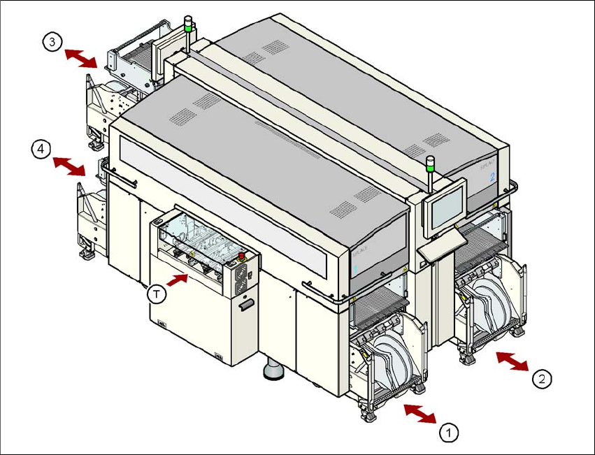
Up to four SIPLACE X-series component trolleys can be docked into the machines from the
SIPLACE X-series. The locations are numbered as shown in the diagram below.
3
Fig. 3.10 - 1 Component trolley locations, SIPLACE X-series
(1) Location 1
(2) Location 2
(3) Location 3
(4) Location 4
(T) PCB direction of travel
The component trolleys are stand-alone modules that can be set up with feeders at an external
set-up area. This means that the production process only has to be interrupted briefly in order to
change the component trolley.
User manual SIPLACE X-series Technical data for the machine
From software version SR.70x.xx 01/2011 EN edition SIPLACE X-series component trolley
197
3
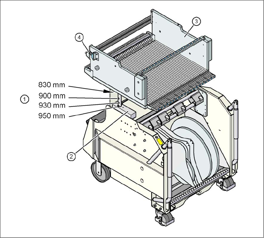
Fig. 3.10 - 2 Component trolley, SIPLACE X-series with a PCB conveyor height of 950 mm
3
(1) Holes for the PCB conveyor heights 900, 930 and 950 mm in the guide columns. For the
830 mm conveyor height, the component table lies on the block (2).
(2) Supporting block
(3) Component table
(4) Contact for switching the safety switch in the component trolley docking unit
Technical data for the machine User manual SIPLACE X-series
SIPLACE X-series component trolley From software version SR.70x.xx 01/2011 EN edition
198
3.10.1 Structure
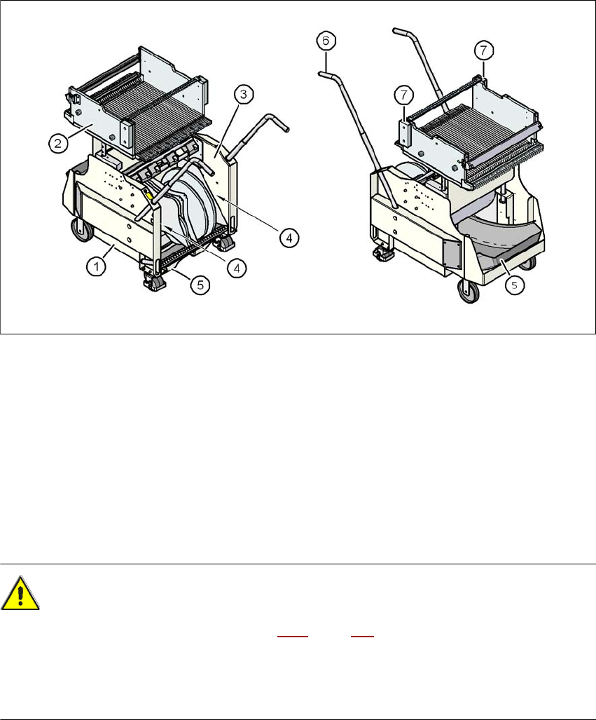
The component trolley essentially consists of the chassis, the component table for holding the
feeder modules, the tape reel container and the waste tape container.
3
Fig. 3.10 - 3 Component trolley, SIPLACE X-series, front and back view
(1) Chassis
(2) Component table
(3) Tape container
(4) Slot for holding set-up lists
(5) Waste tape container
(6) Handle
(7) Hand guard
CAUTION 3
→ Follow the safety instructions in Section 5.8.2
, page 322, when you pull the waste tape con-
tainer out of the component trolley.
– The handles must only be used to push the component trolley.
→ Use a fork-lift if you want to transport the component trolley or lift it from the pallet.