00196504-02_UM_X-Serie_SR70X_EN.pdf - 第205页
User manual SIPLACE X-series Technical data for the machine From software version SR.70x.xx 01/2011 EN edition SIPLACE X-series component trolley 205 3.10.8 T ape container , SIPLACE X-series 3.10.8.1 Description The tap…
Technical data for the machine User manual SIPLACE X-series
SIPLACE X-series component trolley From software version SR.70x.xx 01/2011 EN edition
204
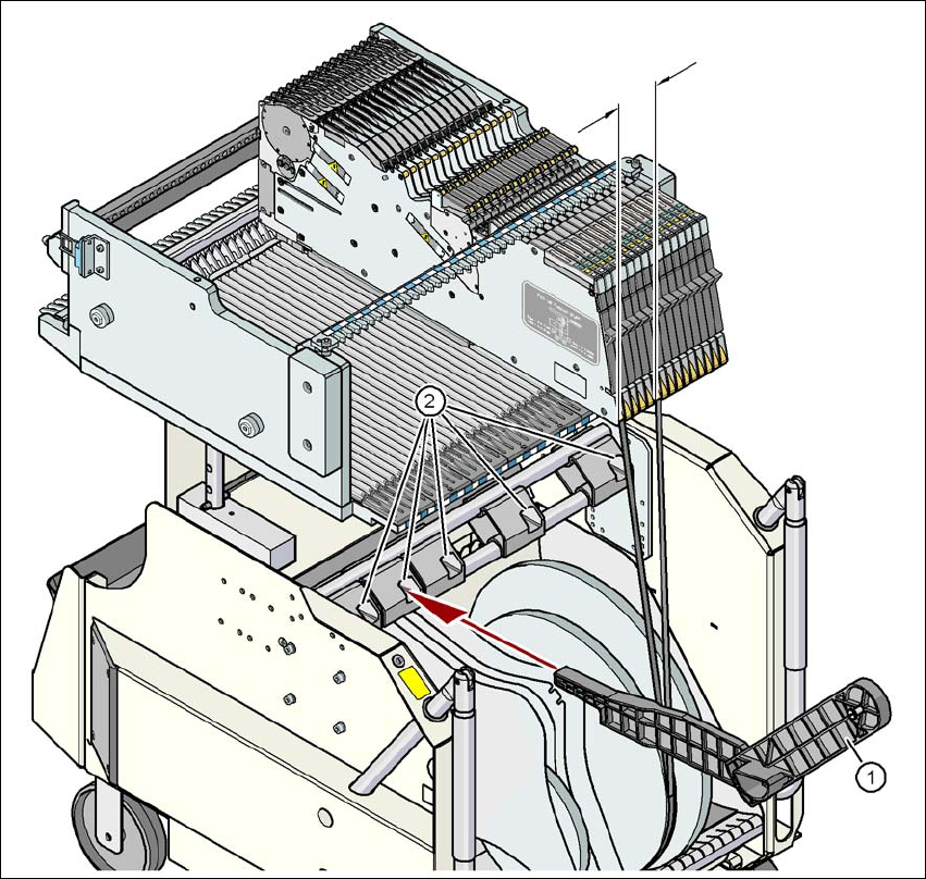
3.10.7 Mount for additional tape reel
3
Fig. 3.10 - 8 Support for an additional tape reel (X-series)
(1) Support for an additional tape reel, item no. 00141217-xx
(2) Mounting device for the support
X-series feeder modules can process component tapes without problems if the lateral offset be-
tween the feeder module and the tape reel does not exceed 60 mm. If a predefined set-up means
that the maximum permitted offset cannot be maintained, we recommend that you use the mount
for an additional tape reel (item 1). Simply insert the mount into the holder (item 2) and push it until
the offset is less than the maximum permitted value of 60 mm. The component trolley has 5 hold-
ers in total. Each tape reel mount can hold 2 tape reels, which means that up to ten 15" (381 mm)
reels can be positioned above the tape container.
max. 60 mm
User manual SIPLACE X-series Technical data for the machine
From software version SR.70x.xx 01/2011 EN edition SIPLACE X-series component trolley
205
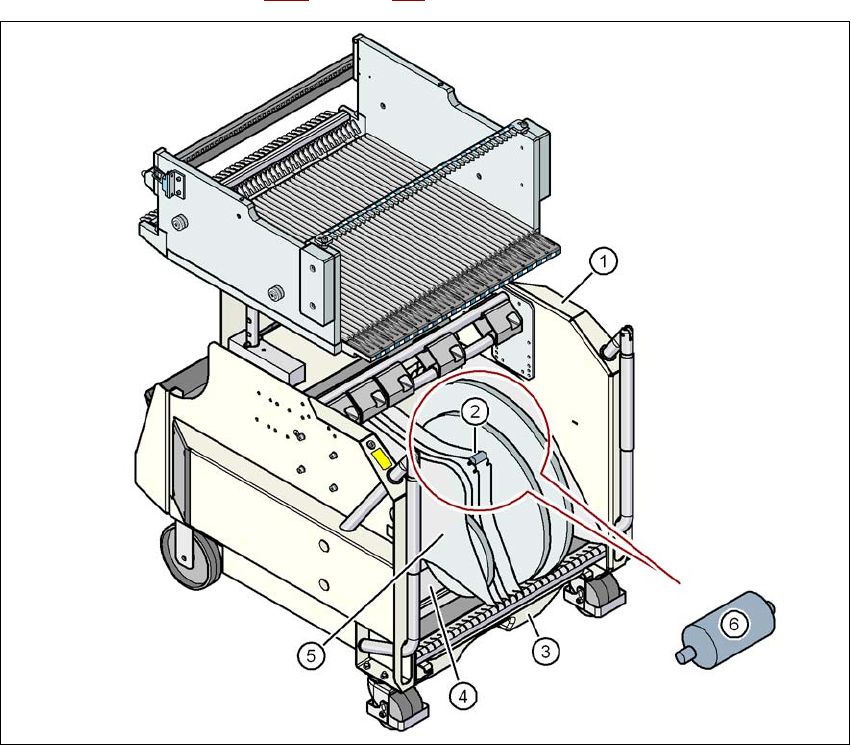
3.10.8 Tape container, SIPLACE X-series
3.10.8.1 Description
The tape container can hold reels up to 19" (483 mm) in diameter. The insertion of separating
plates is described in Section 5.9.5
on page 326.
3
Fig. 3.10 - 9 Component trolley, SIPLACE X-series, with tape container
(1) Component trolley
(2) Position of the quick-release axles
(3) Waste tape container
(4) Tape container
(5) Separating plate
(6) Quick-release axle (enlarged)
Technical data for the machine User manual SIPLACE X-series
SIPLACE X-series component trolley From software version SR.70x.xx 01/2011 EN edition
206
3.10.8.2 Maximum tape reel diameter in relation to the PCB conveyor height
3
PLEASE NOTE: 3
X-series component trolleys do not generally need quick-release axles. However, if the "Timeout"
error message occurs increasingly on the X feeder module, we recommend that you do use
quick-release axles.
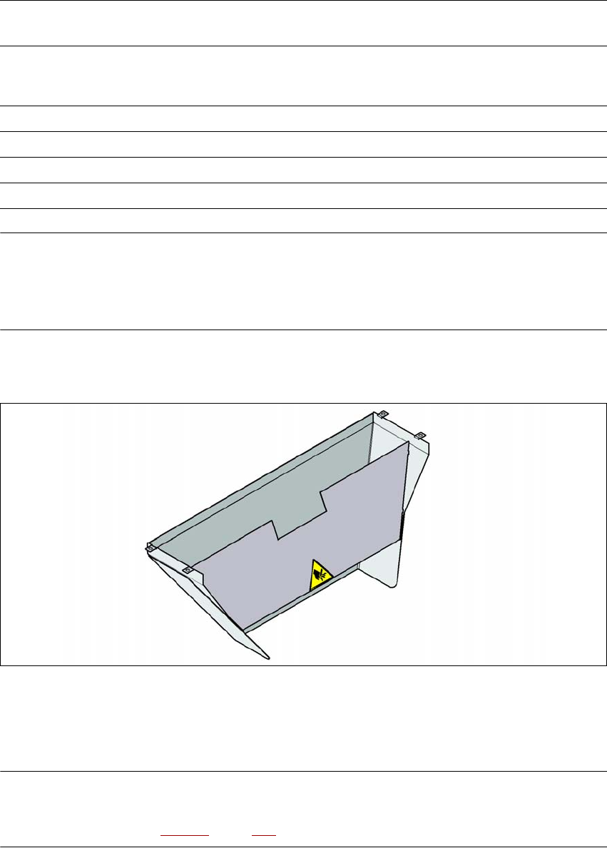
3.10.9 Used tape chute
3
Fig. 3.10 - 10 Used tape chute for the component trolley docking unit
Depending on the PCB conveyor height, the length of the waste tape chute can be set so that the
pieces of tape are diverted directly into the waste tape container of the component trolley.
PLEASE NOTE 3
The used tape chute for the X-series can only be installed on the component trolley docking unit
for the X-series (see Fig. 5.15 - 3, page 346).
Without mount for the
additional tape reel
With mount for the
additional tape reel
PCB conveyor height
of the CO trolley
Tape reel diameter Tape reel diameter
without quick-release axle with quick-release axle
830 mm 17" 15" < 15"
900 mm 19" 17" 15"
930 mm 19" 19" 17"
950 mm 19" 19" 19"