00196504-02_UM_X-Serie_SR70X_EN.pdf - 第22页
Introduction User manual SIPLACE X-series Description of the machine From software version SR.70x.xx 01/2011 EN edition 22 1.1.5 SIPLACE X2 The X2 placement machine has one gantry per pl acement area. This allo ws the fo…

User manual SIPLACE X-series Introduction
From software version SR.70x.xx 01/2011 EN edition Description of the machine
21
1.1.3 SIPLACE X4 LED Placer
The X4 LED placer is equipped with four gantries, two gantries for each placement area (PA). This
allows the following placement head configurations on the X4 LED placer:
a) Placement area 1
b) Placement area 2
The performance data is the same as for X4 placement machines. They can be found in Section
3.1
, page 101.
1.1.4 SIPLACE X3
The X3 placement machine has 3 gantries, 2 of which are in placement area 1 and one is in place-
ment area 2. This allows the following placement head configurations on the X3 placement ma-
chine:
a) Placement area 1
b) Placement area 2
The performance data can be found in Section 3.1 on page 101.
1
Placement heads PA2
b
Placement heads PA1
a
C&P20 / C&P20 CPP / CPP
C&P20 / C&P20 yes no
CPP / CPP yes yes
1
Placement heads
PA2
b
Placement heads PA1
a
C&P20 / C&P20 CPP / CPP CPP/TH TH/TH
C&P20 yes no no no
CPP yes yes no no
TH yes yes yes yes

Introduction User manual SIPLACE X-series
Description of the machine From software version SR.70x.xx 01/2011 EN edition
22
1.1.5 SIPLACE X2
The X2 placement machine has one gantry per placement area. This allows the following place-
ment head configurations:
a) Placement area 1
b) Placement area 2
The performance data can be found in Section 3.1 on page 101.
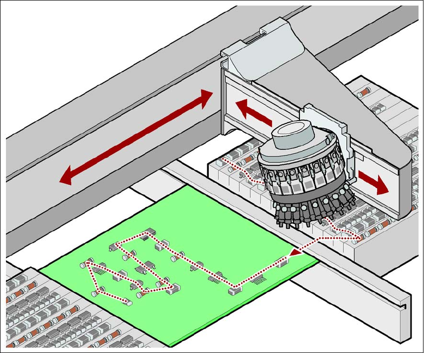
1.1.6 The SIPLACE principle
The placement heads fetch the components from the fixed feeder modules on the component trol-
ley or from the trays in the matrix tray changer, and place the PCBs, which are also stationary. The
placement machines from the X-series have two placement areas:
– on the single conveyor, one or two PCBs can be placed concurrently.
– on the dual conveyor, up to four PCBs can be placed concurrently.
The principle of the "stationary component supply" and "stationary PCB", which has proved most
suitable for all SIPLACE machines, has a number of significant advantages:
– There are no downtimes for topping up components or splicing tapes.
– The vibration-free component feeder means that even the smallest components (e.g. 01005)
are picked up reliably.
– The PCB, which does not move during the placement process, prevents the components slip-
ping.
– The combination of placement heads with nozzle changers always guarantees an optimum
nozzle configuration for every placement process, thus minimizing traversing paths and opti-
mizing the placement sequence.
High flexibility, cost-effectiveness and set-up reliability combine to ensure that the SIPLACE X-se-
ries provides high productivity. Minimum down times increase utilization and thus help to increase
productivity.
1
Placement heads
PA2
b
Placement heads PA1
a
C&P20 CPP TH
C&P20 yes no no
CPP yes yes no
TH yes yes yes
User manual SIPLACE X-series Introduction
From software version SR.70x.xx 01/2011 EN edition Description of the machine
23
1
Fig. 1.1 - 1 Placement principle using the Collect&Place method
1
1
1.1.7 New options and performance features
The following new options are available to extend the machine's functionality:
1.1.7.1 SIPLACE MultiStar (CPP) and the new standard component camera, type 30
The new type 30 component camera supersedes the old type 29 component camera previously
installed on the CPP head. It can be used for prototype production with 01005 components.
1.1.7.2 3D coplanarity sensor
From software release SR.705.03 onwards, the coplanarity measurement is integrated into the
station software. The 3D coplanarity sensor can be installed at the following locations on X4, X3
and X2 placement machines: