00196504-02_UM_X-Serie_SR70X_EN.pdf - 第228页
Setting up and commissioning User manual SIPLACE X-series Setting up the machine From software version SR.70x.xx 01/2011 EN edition 228 4.3.3 T ools an d equipment Y o u will need the following tool s and equipment to ad…
User manual SIPLACE X-series Setting up and commissioning
From software version SR.70x.xx 01/2011 EN edition Setting up the machine
227
4.3 Setting up the machine
4.3.1 PCB conveyor height on the machine
The machine can be set to the following PCB conveyor heights:
830 mm ± 15 mm 4
900 mm ± 15 mm 4
930 mm ± 15 mm (Standard height) 4
950 mm ± 15 mm (SMEMA height) 4
PLEASE NOTE 4
The PCB conveyor height is the distance between the top edge of the PCB conveyor belt and the
bottom edge of the machine feet.
4.3.2 Warning instructions
DANGER 4
Only ASM AS engineers or qualified people are permitted to set up and commission the machine.
→ Always follow the applicable accident prevention regulations.
→ Never lie beneath the machine in order to attach the machine feet. All the modules and parts
can be fitted from the spaces for the component tables. If you nevertheless have to carry out
assembly work underneath the machine, then you must secure the machine by suitable
means. The fork-lift must not be used as the only support.
→ Make sure that the gantries are positioned over the PCB conveyor area so that you do not
restrict your head movement during assembly, thus excluding the risk of injury.
→ Two people will be needed to adjust the height of the machine:
– one person to carry out the necessary assembly work,
– the other person to watch the raised machine during assembly and ensure that it does
not move.
→ Wear special safety boots to protect your feet. Each machine foot weighs approx. 20 kg.

Setting up and commissioning User manual SIPLACE X-series
Setting up the machine From software version SR.70x.xx 01/2011 EN edition
228
4.3.3 Tools and equipment
You will need the following tools and equipment to adjust the height of your machine:
– Fork wrench, size 36, item no. 00096286-01
Size 36 for the adjusting screw M24x2x120 to adjust the height of the machine feet 4
– Hook wrench 135 - 145 for adjusting the middle machine feet
Item no. 00376519-xx 4
– Single-ended spanner, size 65, item no. 00353827-01
Size 65 for the hexagon lock nut M24 on the middle machine foot 4
– Allen key, size 10, item no. 00373926-01
for hexagon socket head screws M12x80 for fixing the spacers for the middle machine feet4
– Allen key, size 19, item no. 00373928-01
for hexagon socket head screw M24x90 for temporarily clamping the four outer machine
feet clamps 4
– Torque wrench with hexagonal pin, size 19, tightening torque 130 Nm
for permanently fitting the four outer machine feet
– Fork-lift
Fork length: min. 1800 mm 4
Carrying capacity: min. 6000 kg 4
Width between forks: see Fig. 4.3 - 1
, page 229 4
– Spirit level : Accuracy 0.02 mm/m
– Air cushion transport system: SIPLACE HSxx, item no. 00119002-xx
User manual SIPLACE X-series Setting up and commissioning
From software version SR.70x.xx 01/2011 EN edition Setting up the machine
229
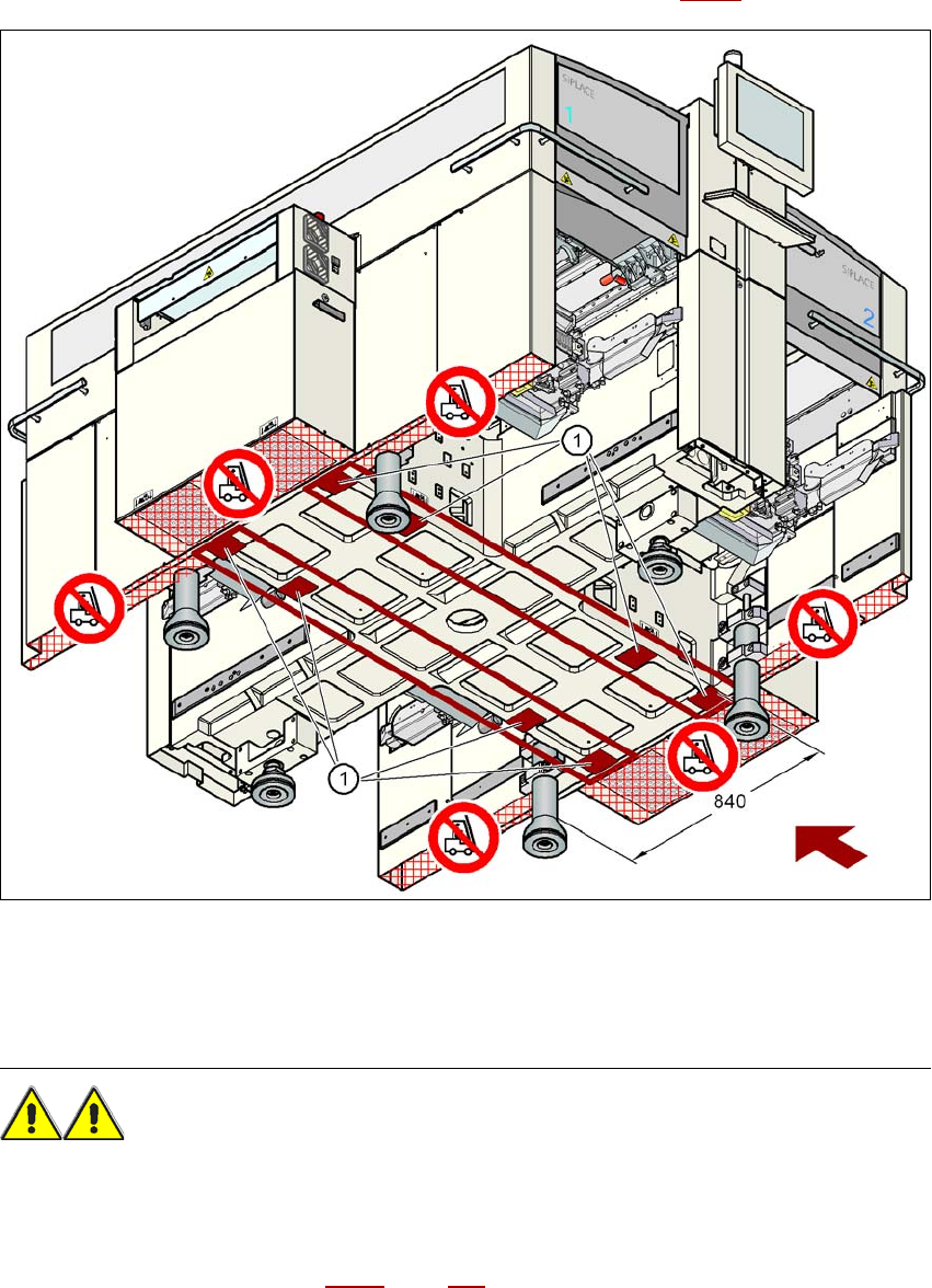
4.3.4 Presetting the PCB conveyor height
→ Push the forks of the fork-lift under the machine, as shown in Fig. 4.3 - 1.
4
Fig. 4.3 - 1 Contact surfaces - Forks parallel to the direction of PCB transport
(1) Contact surfaces for the forks of the fork-lift
WARNING 4
Please note the following points before you raise the machine in order to avoid irreversible dam-
age to the machine:
– Open the forks just wide enough to position them between the two machine feet (the attach-
ment points are shown in Fig. 4.3 - 1
, page 229). The machine feet are 776 mm apart. NEVER