00196504-02_UM_X-Serie_SR70X_EN.pdf - 第234页
Setting up and commissioning User manual SIPLACE X-series Setting up the machine From software version SR.70x.xx 01/2011 EN edition 234 → Fix each spacer using four hexagon socket head screws M12x80 (see point 4 in Fig .…
User manual SIPLACE X-series Setting up and commissioning
From software version SR.70x.xx 01/2011 EN edition Setting up the machine
233
– The opening in the spacer on the power supply side points against the direction of PCB
transport (see point 3 in Fig. 4.3 - 3
on page 231).
→ Fix each spacer using four hexagon socket head screws M12x80 (see point 4 in Fig. 4.3 - 4
,
page 232
). using the size 10 mm screwdriver bit.
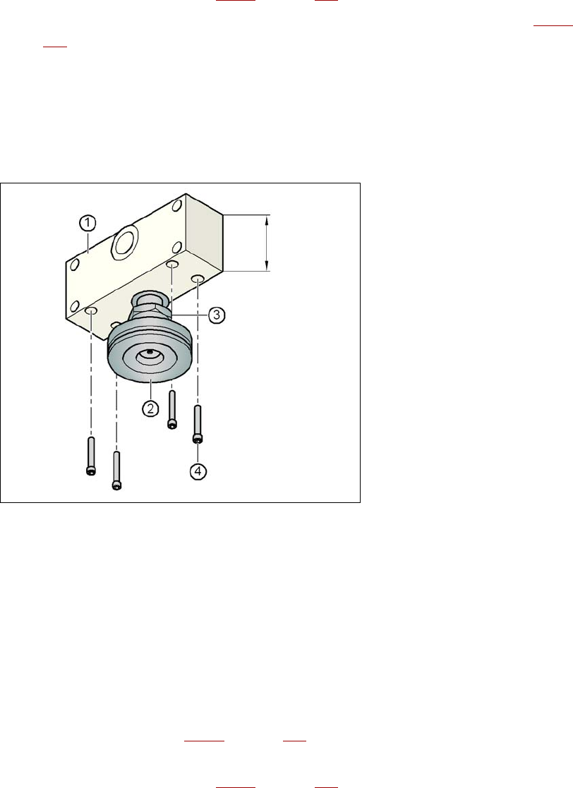
Setting the PCB conveyor height to 930 mm and 950 mm 4
You will also need the spacer for PCB conveyor heights of 930 mm and 950 mm.
→ Align the spacer so that the 122.5 mm side is vertical and the hole for the middle machine foot
points downwards.
4
Fig. 4.3 - 5 Alignment of the spacer for transport heights of 930 and 950 mm
4
(1) Spacer height 122.5 mm
(2) Machine foot
(3) M24 lock nut
(4) Hexagon socket head screw M12x80, 4x
→ Screw the thread of the middle machine foot into the hole on the underside of the spacer.
→ Align the two spacers as follows:
– The opening in the spacer on the pneumatic unit side points in the direction of PCB trans-
port (see point 4 in Fig. 4.3 - 3
on page 231).
– The opening in the spacer on the power supply side points against the direction of PCB
transport (see point 3 in Fig. 4.3 - 3
on page 231).
122.5 mm
Setting up and commissioning User manual SIPLACE X-series
Setting up the machine From software version SR.70x.xx 01/2011 EN edition
234
→ Fix each spacer using four hexagon socket head screws M12x80 (see point 4 in Fig. 4.3 - 5,
page 233
) using the size 10 mm screwdriver bit.
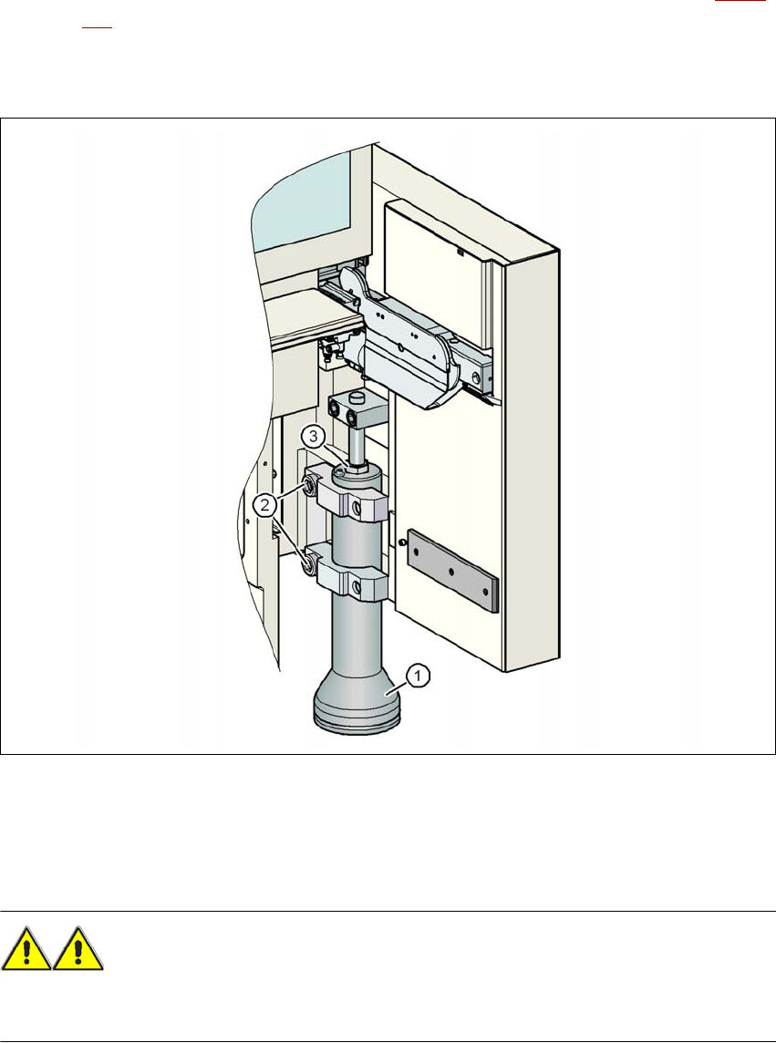
4.3.4.2 Presetting the height of the outer machine feet
4
Fig. 4.3 - 6 Presetting the height of the outer machine feet
(1) Machine foot - 2 versions
(2) M24x90 hexagon socket head screw
(3) M24x2x120 adjusting screw
WARNING 4
When you loosen the hexagon socket head bolts, make sure that your hands and feet are not
beneath the machine foot to minimize the risk of injury. Each machine foot weighs approx. 20 kg.

User manual SIPLACE X-series Setting up and commissioning
From software version SR.70x.xx 01/2011 EN edition Setting up the machine
235
→ Use the 19 mm bit to loosen the two hexagon socket head screws M24x90 (item 2 in Fig.
4.3 - 6
, page 234), and allow the outer machine foot (item 1 in Fig. 4.3 - 6, page 234) to slide
down slowly as far as the stop.
→ Insert the correct machine foot for the required PCB conveyor height.
There are two versions of the outer machine feet: 4
– outer machine foot for the PCB conveyor height of 830 mm, length 369 mm,
item no. 03041008-01 (item 1 in Fig. 4.3 - 3
, page 231)
– outer machine foot for the PCB conveyor heights of 900, 930 and 950 mm, length
439 mm, item no. 03000890-02 (item 2 in Fig. 4.3 - 3
, page 231)
→ Preset the height for each of the outer machine feet.
The distance between the underside of the machine foot and the bottom edge of the machine
frame should be as follows:
→ Use the size 36 fork wrench to turn the adjusting screw M24x2x120 (item 3 in Fig. 4.3 - 6
,
page 234
) until you obtain the distance values given in the above table for the particular trans-
port height.
→ Now use the fork-lift to carefully lower the machine until the machine feet touch the floor
evenly. There should always be a second person present to ensure that the machine remains
stable while it is being lowered. It may be necessary to loosen the outer machine feet clamps
slightly.
→ Continue carefully lowering the machine until the outer machine feet touch the screws
M24x2x120 (item 3 in Fig. 4.3 - 6
, page 234) for adjusting the height.
→ Make sure that the middle machine feet (see point 2 in Fig. 4.3 - 3
, page 231) do not yet touch
the floor. If necessary, screw the middle machine feet into the machine or spacer slightly.
PLEASE NOTE 4
A description of how to definitively adjust the machine can be found in Section 4.3.18
on page
279.
PCB conveyor height Distance from underside of machine foot
to bottom edge of machine frame
830 mm 120 mm
900 mm 190 mm
930 mm 220 mm
950 mm 240 mm