00196504-02_UM_X-Serie_SR70X_EN.pdf - 第237页
User manual SIPLACE X-series Setting up and commissioning From software version SR.70x.xx 01/2011 EN edition Setting up the machine 237 4.3.6 Fitting the output conveyor 4.3.6.1 T ools – Allen keys, DIN 91 1, set – Phill…

Setting up and commissioning User manual SIPLACE X-series
Setting up the machine From software version SR.70x.xx 01/2011 EN edition
236
4.3.5 Fitting the extension kits to the machine frame
4.3.5.1 Fitting the extension kit on the PCB output side
When the machine is delivered, the extension kit on the PCB output side and the PCB output -con-
nveyor are dismantled. The procedure for attaching the extension kit to the PCB output side is as
follows:
– Fitting the output conveyor
see Section 4.3.6, page 237
– Fitting the extension kit on the PCB output side see Section 4.3.7, page 238
– Installing the axis unit see Section 4.3.8, page 244
– Fitting the indicator lamp see Section 4.3.14, page 268
– Integrating the machine into the line see Section 4.3.17, page 276
– Making final adjustments to the machine see Section 4.3.18, page 279
4.3.5.2 Fitting the extension kit on the PCB input side
If the extension kit on the PCB input side was also removed for ease of transportation, you will
have to carry out the following steps before integrating the machine into the line (see Section
4.3.17
, page 276):
– Fitting the input conveyor
see Section 4.3.9, page 252
– Fitting the extension kit on the PCB input side see Section 4.3.10, page 254
– Installing the box PC unit on the SIPLACE X4I see Section 4.3.12, page 263
– Installing the axis unit see Section 4.3.13, page 266
– Fitting the indicator lamp see Section 4.3.14, page 268
– Integrating the machine into the line see Section 4.3.17, page 276
– Making final adjustments to the machine see Section 4.3.18, page 279
User manual SIPLACE X-series Setting up and commissioning
From software version SR.70x.xx 01/2011 EN edition Setting up the machine
237
4.3.6 Fitting the output conveyor
4.3.6.1 Tools
– Allen keys, DIN 911, set
– Phillips screwdriver, size 1
4.3.6.2 Assembly
4
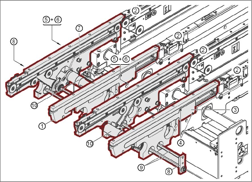
Fig. 4.3 - 7 Output conveyor - dual conveyor
(1) Rail, output conveyor
(2) Rail, processing conveyor 2
(3) Cable cover 20 x 200
(4) Countersunk screw, ISO 7046, M3x6, 2x per cable cover
(5) Cable cover 20 x 310
(6) Fillister head screw DIN 912, M3x5, 1x per cable cover
(7) Fillister head screw DIN 912, M6x16, and washer, 4x per rail
(8) Guide for hexagonal shaft
(9) Hexagonal shaft (single conveyor: one, dual conveyor: two)
(10) Drive unit

Setting up and commissioning User manual SIPLACE X-series
Setting up the machine From software version SR.70x.xx 01/2011 EN edition
238
→ Remove the cable covers (items 3 and 5 in Fig. 4.3 - 7, page 237) from the rails (item 1 in Fig.
4.3 - 7
, page 237) of the output conveyor.
→ Carefully place the rail (item 1 in Fig. 4.3 - 7
, page 237) against the rail on the processing
conveyor (item 2 in Fig. 4.3 - 7
, page 237).
CAUTION 4
Be careful not to cut through any of the light barrier or drive motor cables.
→ Fix each rail using 4 fillister head screws M6x16 and the associated washers (item 7 in Fig.
4.3 - 7
, page 237).
→ Connect the power cable to the light barriers and drive motors.
→ Fix the cable covers in place (item 3 and 5 in Fig. 4.3 - 7
, page 237).
→ Introduce the hexagonal shaft (item 9 in Fig. 4.3 - 7
, page 237) into the drive unit (item 10 in
Fig. 4.3 - 7
, page 237).
→ Make sure that the hexagonal shaft guide (item 8 in Fig. 4.3 - 7
, page 237) always points to-
wards the conveyor side wall to which the drive unit (item 10 in Fig. 4.3 - 7
, page 237) is fixed.
4.3.7 Fitting the extension kit on the PCB output side
4.3.7.1 Tools
– Allen keys, DIN 911, set
– Machine key