00196504-02_UM_X-Serie_SR70X_EN.pdf - 第24页
Introduction User manual SIPLACE X-series Description of the machine From software version SR.70x.xx 01/2011 EN edition 24 1 The 3D cop lanarity sens or uses a la ser line to sc an the component le ads or balls. When com…
User manual SIPLACE X-series Introduction
From software version SR.70x.xx 01/2011 EN edition Description of the machine
23
1
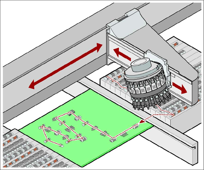
Fig. 1.1 - 1 Placement principle using the Collect&Place method
1
1
1.1.7 New options and performance features
The following new options are available to extend the machine's functionality:
1.1.7.1 SIPLACE MultiStar (CPP) and the new standard component camera, type 30
The new type 30 component camera supersedes the old type 29 component camera previously
installed on the CPP head. It can be used for prototype production with 01005 components.
1.1.7.2 3D coplanarity sensor
From software release SR.705.03 onwards, the coplanarity measurement is integrated into the
station software. The 3D coplanarity sensor can be installed at the following locations on X4, X3
and X2 placement machines:

Introduction User manual SIPLACE X-series
Description of the machine From software version SR.70x.xx 01/2011 EN edition
24
1
The 3D coplanarity sensor uses a laser line to scan the component leads or balls. When combined
with the SIPLACE TwinHead, this method returns faster measuring results for BGAs, for example.
1.1.7.3 Type 24 multicolor camera
From this software version onwards, the type 24 multicolor camera can be installed in place of the
standard PCB camera for measuring fiducials and ink spots. There is a choice of three illumination
modes to improve the contrast for fiducials or ink spots.
1.1.7.4 SIPLACE X4 LED placer
From software version SR.705 onwards we can supply a configuration for the SIPLACE X4 place-
ment machines that is specially tailored to the customer's needs when producing these LED back-
light units.
The SIPLACE X4 LED placer is based on a SIPLACE X4 placement machine with four C&P20 or
CPP placement heads. Special component tables are installed in place of CO trolleys. Special,
customer-specific bowl feeders supply the LED components. If only one bowl feeder is set up at
a location, there must be no tape cutter installed at this location. The feeder modules receive op-
timum support from the station software - with the empty feeder function, for example. Other
SIPLACE X feeder modules can also be set up. The single and dual conveyors process printed
circuit boards up to 850 mm long.
Placement machine Location
SIPLACE X2, SIPLACE X3 3
SIPLACE X4 2 or 3
User manual SIPLACE X-series Introduction
From software version SR.70x.xx 01/2011 EN edition Description of the machine
25
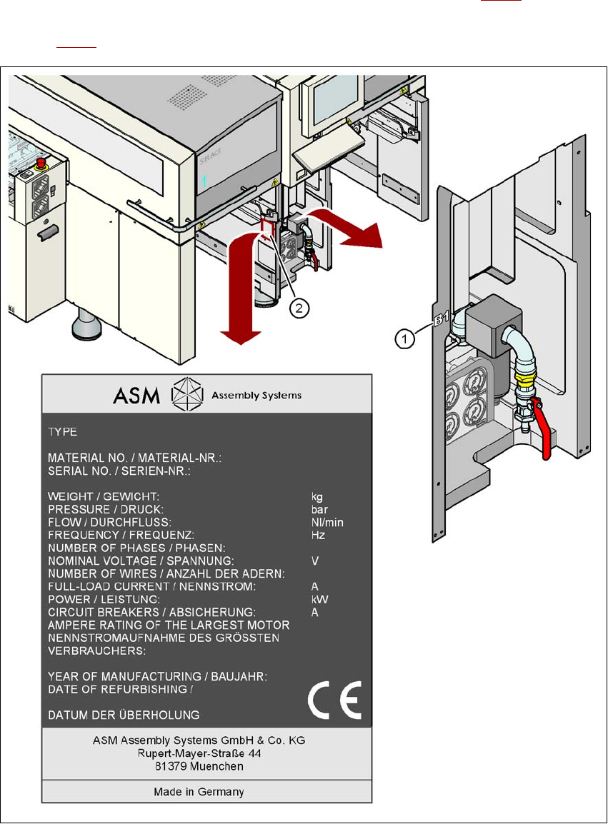
1.1.8 Serial number of the machine
The serial number of the machine can be found in two different places.
– The serial number, without leading zeros, e.g. B-1, is struck on the left-hand side of the ma-
chine frame, on the same side as the pneumatic unit (see item 1 in Fig. 1.1 - 2
).
– With leading zeros, e.g. B-001, the serial number is punched in the rating plate (see item 2 in
Fig. 1.1 - 2
).
1
Fig. 1.1 - 2 Places with the serial number on the X4 machine